
ning
-
Posts
329 -
Joined
-
Last visited
Content Type
Forums
Store
Crowdfunding
Applications
Events
Raffles
Community Map
Everything posted by ning
-

OrangePi 3b RK3566 Help with name of pins
ning replied to maximilian fletkar's topic in Radxa Rock Pi E
yuo can't use GPIO as power supply, will break soc. -
OrangePi 3b RK3566 Help with name of pins
ning replied to maximilian fletkar's topic in Radxa Rock Pi E
there is not reset pin on this connecter? unless you change I2C1_SCL_M0/I2C1_SDA_M0 to reset pin, according to your panel's interface define.
-
OrangePi 3b RK3566 Help with name of pins
ning replied to maximilian fletkar's topic in Radxa Rock Pi E
I think OPI 3B supports eDP panel, but sitronix is MIPI panel, right? -
Hardware accelerated video decoding fails with gstreamer on Radxa Zero SBC
ning replied to langweiler's topic in Radxa Zero
develop effort on Amlogic HW dec looks stopped, and not usable now. please forget this driver. -
Help wanted to test a new OpenVFD alternative
ning replied to Jean-Francois Lessard's topic in Amlogic meson
in fd6551 data sheet, page 7, it says: clk better lower than 100K. I don't know how to set i2c-rockchip or i2c-gpio to 100k or lower? i2c-gpio,delay-us = <10>; ? http://www.fdhisi.com/down/upload/20191023/1571794231.pdf -
Help wanted to test a new OpenVFD alternative
ning replied to Jean-Francois Lessard's topic in Amlogic meson
VDD has 3.3V.. I have no idea now. -
Help wanted to test a new OpenVFD alternative
ning replied to Jean-Francois Lessard's topic in Amlogic meson
use i2c1, error timeout, use gpio-i2c error no such device. let me check power VDD. -
Help wanted to test a new OpenVFD alternative
ning replied to Jean-Francois Lessard's topic in Amlogic meson
[ 23.946809] tm16xx 4-0034: Display initialized successfully i2c4 is bad, any address can have good write result. -
Help wanted to test a new OpenVFD alternative
ning replied to Jean-Francois Lessard's topic in Amlogic meson
i2c1 { /omit-if-no-ref/ i2c1_xfer: i2c1-xfer { rockchip,pins = /* i2c1_scl */ <0 RK_PB3 1 &pcfg_pull_none_smt>, /* i2c1_sda */ <0 RK_PB4 1 &pcfg_pull_none_smt>; }; }; phandle 0x35 is gpio0 -
Help wanted to test a new OpenVFD alternative
ning replied to Jean-Francois Lessard's topic in Amlogic meson
it's easy to try fd655 and i2c-gpio. and I read Android dts many times, not findings. jianpian.dts -
Help wanted to test a new OpenVFD alternative
ning replied to Jean-Francois Lessard's topic in Amlogic meson
after read spec, 7 SEG pins for 7 LEDs (LAN, WIFI...etc) and 4 DIG pins control 4 digital. 5 DIG pins are controlled by 66h~6eh, while 4 digitals how to control seg pins? use 1 DIG pin? I guess Yes. each digital has 7 LEDs, and there also 7 Seg LED. write number to DIG register, at least 1 LED will on. OK. 1 DIG pin controls 1 digtal, and each digital has 7 seg, 1 seg connects to 1 SEG pin. there are 5 digitals (one virtual), and they share SEG pins. So let me check VDD. -
Help wanted to test a new OpenVFD alternative
ning replied to Jean-Francois Lessard's topic in Amlogic meson
I checked your code, the i2c address is correct, brightness register is correct. dig registers are correct. it should work, but no. I don't know why, let me check fd6551's VDD. if there no power, will it answer I2C command, I2C write should return -1, but no error in dmesg. -
Help wanted to test a new OpenVFD alternative
ning replied to Jean-Francois Lessard's topic in Amlogic meson
use sysfs leds interface to control it but it doesn't show any thing... -
Help wanted to test a new OpenVFD alternative
ning replied to Jean-Francois Lessard's topic in Amlogic meson
it's on i2c4. I don't see I2c error during probe. please let me know what to do next! &i2c4 { status = "okay"; vfd@24 { compatible = "fdhisi,fd6551"; reg = <0x24>; tm16xx,digits = [04 03 02 01]; tm16xx,segment-mapping = [03 01 02 06 04 05 00]; #address-cells = <2>; #size-cells = <0>; led@0,0 { reg = <0 0>; function = LED_FUNCTION_ALARM; }; led@0,1 { reg = <0 1>; function = LED_FUNCTION_USB; }; led@0,3 { reg = <0 3>; function = "play"; }; led@0,2 { reg = <0 2>; function = "pause"; }; led@0,4 { reg = <0 4>; function = "colon"; }; led@0,5 { reg = <0 5>; function = LED_FUNCTION_LAN; }; led@0,6 { reg = <0 6>; function = LED_FUNCTION_WLAN; }; }; }; -
Help wanted to test a new OpenVFD alternative
ning replied to Jean-Francois Lessard's topic in Amlogic meson
the correct part is VFD device is fdhisi,fd6551, I see the chip on board. but the i2c gpios are icorrect.. -
Help wanted to test a new OpenVFD alternative
ning replied to Jean-Francois Lessard's topic in Amlogic meson
OK, I will try this suggestion. -
Help wanted to test a new OpenVFD alternative
ning replied to Jean-Francois Lessard's topic in Amlogic meson
I don't have vfd.conf. I can try the drivers one by one, then try to write a conf. -
Help wanted to test a new OpenVFD alternative
ning replied to Jean-Francois Lessard's topic in Amlogic meson
I'm happy to and will test your driver on JianPian Rk3566 TV box. -
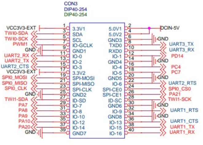
you need to develop your dtbo to support your addon devices. from your description, your device needs a set of SPI pins, and a reset pin. OPI PC plus already provides the pins you want. MOSI SPI0_MOSI / GPIO10 (PIN 19) MISO SPI0_MISO / GPIO9 (PIN 21) SCK SPI0_SCLK / GPIO11 (PIN 23) NSS/Enable SPI0_CE0_N / GPIO8 (PIN 24) then, you need develop a dtbo for your device. 156 &spi0 { 157 status = "okay"; 158 159 YOUR_DEVICE@0 { 160 compatible = "YOUR_DEVICE"; 161 reg = <0>; 162 spi-max-frequency = <50000000>; 163 }; 164 }; if your device use an userspace driver, that not need YOUR_DEVICE@0 node. that all you need to do.
-
you want to add a 2 pin fan to opi5, unfortunitly, PWM port is IO port, it doesn't have enough power to driver your fan, thus would break the GPIO bank, and make whole bank unfunction. thus suggest to directly use 5V power pin. if you have 3 pin fan, you can use a PWM pin to control it speed. in this case, you need write dts code to enable it.
-
Efforts to develop firmware for H96 MAX V56 RK3566 8G/64G
ning replied to Hqnicolas's topic in Rockchip CPU Boxes
@Hqnicolas here is my tree https://github.com/zhangn1985/linux-stable/ -
this msg due to leftover file of armbian packages.
-
you can't use GPIO as power supply for fan, this will break the gpio bank. you can use GPIO as ON/OFF switch for fan, you should use "gpio-fan" driver. https://git.kernel.org/pub/scm/linux/kernel/git/stable/linux.git/tree/Documentation/devicetree/bindings/hwmon/gpio-fan.txt?h=v6.7.8 by this you can use /sys/class/thermal/cooling_deviceX/state control you fan, but if you want to system automatically enable your fan at certan temperature, you need register the fan as a cooling device, for cpu/gpu or hard driver. https://git.kernel.org/pub/scm/linux/kernel/git/stable/linux.git/tree/Documentation/devicetree/bindings/thermal/thermal-cooling-devices.yaml
-
should it use pwm-regulator driver?
-
what's charge pump, is there devicetree yaml to let you know how to use pwm?