going
-
Posts
835 -
Joined
-
Last visited
Content Type
Forums
Store
Crowdfunding
Applications
Events
Raffles
Community Map
Everything posted by going
-
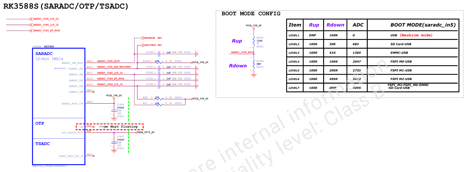
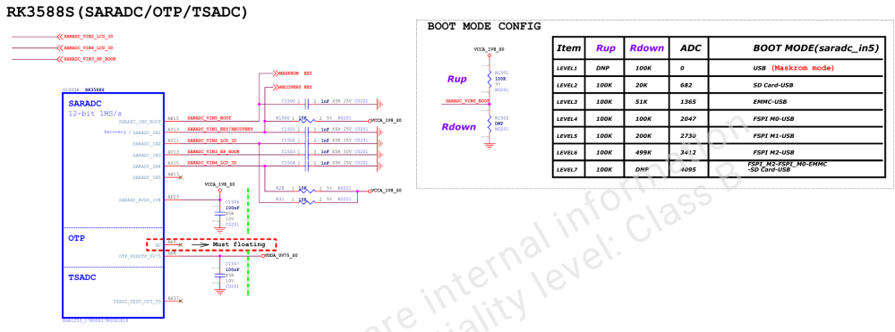
I think he won't give much information in this situation. I have these two boards (OPI-5, OPI-5-plus). They both arrived with a pre-installed loader in SPI-Flash. The loading order on both boards is the same. BootRom searches for the boot code on SPI-flash and downloads it. In other words. If u-boot v2019 is written to the SPI-flash and the bootloader v2025.01 is written to the SD card, I will see the v2019 message in the UART console. Maybe the documentation will give you a hint? This is part of the wiring diagram.
-
I still recommend restoring the original circuit.
-
OPI-5, OPI-5-plus - The connection scheme of the SPI flash memory chip is similar. I did an experiment with OP-5-plus. On a running OS, I erased all mtd-flash using the dd if=/dev/zero of=/dev/mtd command. The device turned into a brick. Downloading from an SD card or NVME has become impossible. Recovery: I downloaded this archive from the official orangepi website: MiniLoader - what is needed for burning Linux images-20241230T170815Z-001.zip The device is in MaskRom mode and the MaskRom button is not pressed. MiniLoader> ls -al итого 6136 drwxr-xr-x 2 leo users 208 янв 1 20:33 . drwxr-xr-x 4 leo users 45 дек 31 16:30 .. -rw-r--r-- 1 leo users 448960 янв 1 1980 MiniLoaderAll.bin -rw-r--r-- 1 leo users 1249 янв 1 1980 rk3588_linux_emmc.cfg -rw-r--r-- 1 leo users 1859 янв 1 1980 rk3588_linux_pcie.cfg -rw-r--r-- 1 leo users 1249 янв 1 1980 rk3588_linux_spiflash.cfg -rw-r--r-- 1 leo users 1249 янв 1 1980 rk3588_linux_tfcard.cfg -rw-r--r-- 1 leo users 4194304 янв 1 1980 rkspi_loader.img -rw-r--r-- 1 leo users 1620480 янв 1 18:53 u-boot-rockchip-spi.bin rkdeveloptool db MiniLoaderAll.bin If your device switches to MaskRom mode on its own and the command returns an error at this stage, the MaskRom button may be defective (it is always pressed). This is an assumption. In my case, I had to press a button, then turn on the power and release the button. Nothing is connected to the device. There is no SD card. There is no HDMI cable. There is no UART. Only the power cable and the USB cable to the PC. Boot_option It is not possible to boot this device if the mtd chip is clean. In my case, I wrote the entire u-boot v2025.01 code to mtd. I built it myself in the Armbian build system without any additional patches. Today, my device loads any image (OS) from all the memory devices I have. Well good luck. With respect to you as a person who knows how to operate a soldering iron.
-
Help: Rkdeveloptool Rockusb rk3588_spl_loader_v1.15.113.bin as miniloader I assume that you have a computer with Linux OS installed. The rkdeveloptool utility is installed or built. Connect your device to this computer using a USB cable. Press the Maskrom button and hold it down to turn on the power on the device. In the next step, you should download the mini loader to your device using the rkdeveloptool utility. rkdeveloptool db rkxx_loader_vx.xx.bin Now the device should come to life and should respond to requests and perform some actions. If you have pre-downloaded and unpacked the u-boot armbian binary package for your device (extract the bootloader file from the package), you can do the following: Just in case, run the clear command. Write the armbian bootloader to the memory chip. For tips on the offset, see the u-boot package script.
-
 https://stpete-mirror.armbian.com/ (St. Petersburg) This mirror works well in the Russian Federation. But how do I make sure that this mirror is automatically selected in the build system itself at the image creation stage? I mean the phase of installing packages in a future image. ... [🔨] Err:5 http://mirror.hostiko.network/armbian bookworm InRelease ... [🔨] Err:5 http://fastmirror.pp.ua/armbian bookworm InRelease ...
 -
leo@bananapim64:~$ sudo nano /etc/apt/sources.list.d/armbian.list http://apt.armbian.com =>> https://stpete-mirror.armbian.com/apt leo@bananapim64:~$ cat /etc/apt/sources.list.d/armbian.list deb [signed-by=/usr/share/keyrings/armbian.gpg] https://stpete-mirror.armbian.com/apt bookworm main bookworm-utils bookworm-desktop leo@bananapim64:~$ sudo apt update Сущ:1 http://deb.debian.org/debian bookworm InRelease Сущ:2 http://security.debian.org bookworm-security InRelease Сущ:3 http://deb.debian.org/debian bookworm-updates InRelease Сущ:4 http://deb.debian.org/debian bookworm-backports InRelease Сущ:5 https://github.armbian.com/configng stable InRelease Пол:6 https://stpete-mirror.armbian.com/apt bookworm InRelease [53,3 kB] Пол:7 https://stpete-mirror.armbian.com/apt bookworm/main all Packages [17,5 kB] Пол:8 https://stpete-mirror.armbian.com/apt bookworm/bookworm-utils arm64 Packages [37,4 kB] Пол:9 https://stpete-mirror.armbian.com/apt bookworm/bookworm-desktop all Packages [7 526 B] Пол:10 https://stpete-mirror.armbian.com/apt bookworm/main arm64 Packages [1 168 kB] Пол:11 https://stpete-mirror.armbian.com/apt bookworm/bookworm-desktop arm64 Packages [15,9 kB] Пол:12 https://stpete-mirror.armbian.com/apt bookworm/bookworm-utils all Packages [3 965 B] Получено 1 304 kB за 9с (149 kB/s) Чтение списков пакетов… Готово Построение дерева зависимостей… Готово Чтение информации о состоянии… Готово Может быть обновлено 4 пакета. Запустите «apt list --upgradable» для их показа.
-
Yesterday, at my test stand, I discovered a malfunction on the banana pi M64. The behavior is exactly the same as that of your board. I found the reason quickly. These were oxidized/weakened contacts on the power supply. When the board starts, the consumption is low. But then all the regulators are turned on, and when the OS starts setting up, consumption increases dramatically. In that place of bad contact, a voltage drop occurs and the board turns off. Soldering iron + screwdriver solved the problem. My power supply is open and I have access to it.
-
I think that there are no nodes in this DTS that can be deleted. Most likely, on the contrary, something needs to be added/changed. In fact, this is quite a difficult job even for an experienced developer. Some things may depend on the firmware. Try to look towards devices officially supported by Armbian.
-
https://docs.banana-pi.org/en/BPI-M2_Ultra/BananaPi_BPI-M2_Ultra Have you tried running any of these many old images? https://docs.banana-pi.org/en/BPI-M2_Ultra/BananaPi_BPI-M2_Ultra#_linux_2
-
Here it may be necessary to check the nodes in the DTS. It may be necessary to add additional missing ones. This is an assumption. Possible reasons for the hangup: 1) The config/boards/bananapim2ultra.csc configuration file for your boards is very simple. The build system applies patches from the patch/u-boot/u-boot-sunxi/ folder. Maybe some are breaking the settings for your board. Try adding these lines to the board configuration file: BOOTBRANCH="tag:v2024.01" BOOTPATCHDIR="u-boot-sunxi/board_${BOARD}" This will force the build system to apply only patches from this folder. 2) We need to make sure that the SD card is working properly. A larger card can be limited in advance. After you have written the image to the card, you can open the gnome-disk utilities and expand the first partition to 16 GB, and then create another new partition from the remaining empty space. 3) You have supplied the power. The board has started loading and the indicator is on. The board stopped loading and the indicator went out. Perhaps the CPU or GPU temperature is detected incorrectly (high) and the OS turns off the power. /boot/armbianEnv.txt file verbosity=10 All that I have written is my assumptions.
-
This is an old core and Armbian does not support it. If for some reason you need version 6.1, then try to build with the BRANCH="legacy" parameter. But I warn you that version 6.1 will be deleted after a while. Recommendations: Assemble the image using BRANCH="edge". Today it is the 6.12 kernel and it will become the current one soon. If you have problems downloading, try changing the debug level to 10. Post it here under the spoiler and please call me as @going.
-
😁👍
-
Can you post your changes here as "git diff" or "git format-patch -1"
-
Warning: H5 processors from the first batches cannot be overclocked to these frequencies. On my device, I was unable to get stable operation at a frequency higher than 1.2Ghz.
-
Yes. I'm hinting at the same thing. We need to make some additional packages. But the build system lacks a simple or general mechanism for assembling/reassembling debian packages.
-
The same problem. And I still can't find a place in the source code where it can be fixed.
-
[ 0.000000] Linux version 6.6.73-current-spacemit (build@armbian) (riscv64-linux-gnu-gcc (Ubuntu 13.2.0-23ubuntu4) 13.2.0, GNU ld (GNU Binutils for Ubuntu) 2.42) #1 SMP PREEMPT_DYNAMIC Tue Jan 21 12:19:25 UTC 2025 [ 0.000000] Machine model: BananaPi BPI-F3 [ 0.000000] SBI specification v1.0 detected [ 0.000000] SBI implementation ID=0x1 Version=0x10003 [ 0.000000] SBI IPI extension detected [ 0.000000] SBI RFENCE extension detected Maybe Patrick @c0rnelius can shed some light on this issue? It's still in development. Please join the development. Code source: https://gitee.com/bianbu-linux Today, only the following has been added to the build system: (spacemit.conf) opensbi, u-boot-spacemit, linux-bianbu But this is not enough for full-fledged work. Welcome!
-
NanoPi Neo2 V1.1 / how to control OTG port power with GPIO 354?
going replied to mdrmdr's topic in Allwinner sunxi
You can also compare the dts after all the patches have been applied in my branch. sunxi-6.6-rebase If you find that something does not match the circuit board and you can fix it, then you can post the fixes (git forat-patch -1) directly here or make a pull request on the github. -
NanoPi Neo2 V1.1 / how to control OTG port power with GPIO 354?
going replied to mdrmdr's topic in Allwinner sunxi
The h5 <-> h3 processors are pin-to-pin compatible. That is, you can solder h3 and solder h5 to this place. After modifying the DTS file for the board, you can make it work. That's the theory. In your case, the difference is probably in the PCB layout. gpio = <0x15 0x01 0x09 0x00>; gpio = <0x42 0x00 0x02 0x00>; You'll have to find some kind of workaround. -
NanoPi Neo2 V1.1 / how to control OTG port power with GPIO 354?
going replied to mdrmdr's topic in Allwinner sunxi
But dtb may have differences. I mean the one that was used on a working device. Extract for both cases and compare. dtc --sort -I fs -O dts /sys/firmware/devicetree/base > dts-out.txt Maybe this will give you a clue. -
@asayed I have been using QEMU KVM + Virtual Machine Manager for over 10 years. Just install the official ubuntu 22.04 server image in the VM and clone the armbian repository inside the VM. With respect. P.S. This allows you to quickly roll back to the snapshot in case of a crash and not ruin your running OS on host. It is necessary to have 45-50 GB of free space inside the VM before the first start.
-
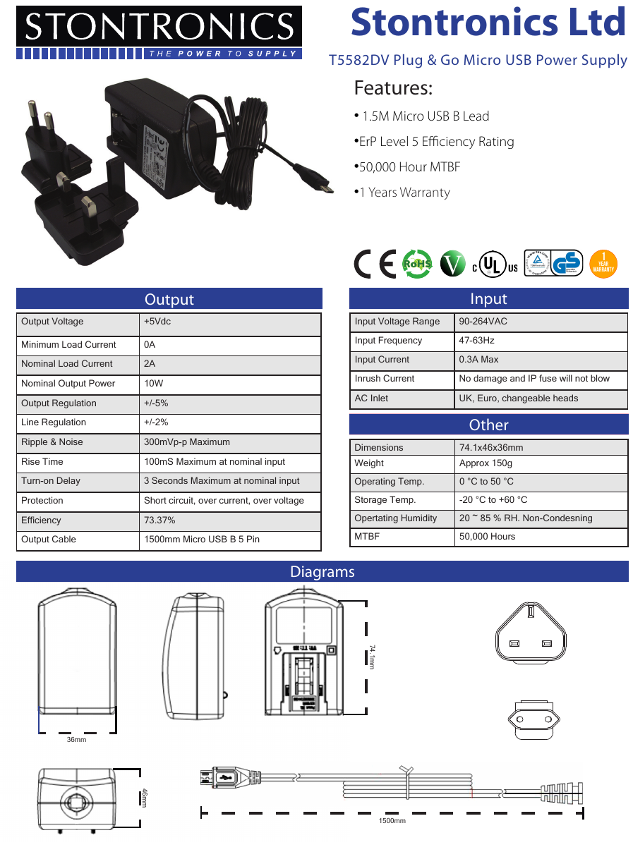
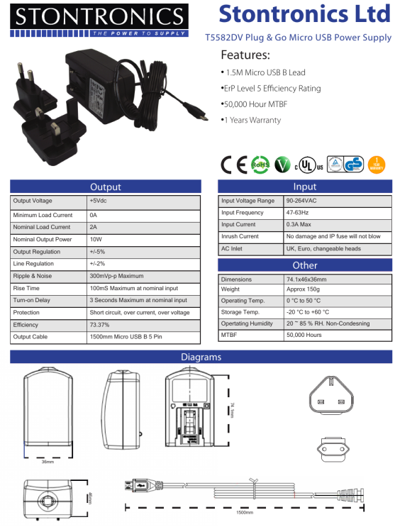
Perhaps nothing needs to be soldered. Try to purchase a 4 amp power supply with a detachable power cable. For example: Power supply <-> USB-microUSB cable <-> Board.
-
1500 mm - It's a long cable. The Council. Shorten the cable and solder a new connector. The connectors are sold disassembled in specialty stores. The connector on the board itself may also be loose or the soldering location may be oxidized (poor contact). It can also be replaced (solder a new one). Maybe it will serve you for a few more years.
-
micro USB is a fairly delicate connector. He might get loose. The power supply circuit on most of these development boards is implemented in a fairly simple way and any additional load can lead to a decrease in the supply voltage in individual circuits. The variation of the actual resistance value from the nominal value in the resistors can lead to both an increase in voltage and a decrease. This leads to the fact that my NVME is working, but it is very hot (increased supply voltage) or, in your case, a malfunction (low supply voltage). This can be cured if you pick up a soldering iron. But for this you need to be well versed in circuit design and have experience in such work. I have encountered such problems when connecting HDD, SSD, NVME via USB-SATA adapter. But never with an SD card. Will you be able to publish the brand of the equipment so that other users can read about this issue?
-
Maybe so: sudo chroot /mnt/ or sudo chroot /mnt/bin/bash or cd /mnt sudo chroot ./bin/bash