Search the Community
Showing results for 'uart rts'.
-
I use NANOPI R1 in one of my projects. Now I need to develop a board to make a physical watchdog from NANOPI R1 itself and an RTC (the NANOPI R1 RTC does not work). I have two possibilities: One is to use the already integrated UART, or use a USB - I2C converter. Using the UART I would communicate the NANOPI with a 328P microcontroller, and from there I would collect the RTC information (with i2c between 328P and RTC), in addition to sending the frequent information to the 328P to keep the watchdog active. Using the I2C, the RTC would be connected to the I2C BUS and I would do the direct query via NANOPI R1, as well as send the frequent information via I2C to the 328P or ATTINY85 (I can use this CI - it have I2C) to keep the watchdog active. I want an opinion: I would like to know how you would do that? Would it be using I2C or using UART? If they were going to use UART, I need the two ports available on NANOPI R1 (because I already use a Nextion HMI on a UART port). So can i use UART_DBG too? What problems can I face?
.jpg.407b3f767109a69fc60ba4cffaeb9985.jpg)
-
Hi, I'm new to the SoC / Armbian world, and I'm trying to connect to my NanoPC-T4 via UART (Armbian 20.11.7 Focal with Linux 5.9.14-rockchip64). I'm using an ADAFRUIT Industries 954 USB-to-TTL serial cable. The NanoPC-T4 pin spec indicates SPI1_TXD/UART4_TX(3V) as pin 19, GND as pin 20, and SPI1_RXD/UART4_RX(3V) as pin 21. I have hooked up my ADAFRUIT accordingly with the white receptacle (RX) to pin 19, the black receptacle (GND) to pin 20, and the green receptacle (TX) to pin 21. The full NanoPC-T4 pin spec is here: http://wiki.friendlyarm.com/wiki/index.php/NanoPC-T4. The kernel command line is as follows: [ 0.000000] Kernel command line: root=UUID=cb1cdae1-67a0-4938-850e-0ca79ecd821c rootwait rootfstype=ext4 bootsplash.bootfile=bootsplash.armbian console=ttyS0,1500000 console=ttyS2,1500000 console=tty1 consoleblank=0 loglevel=1 ubootpart=7fa9e296-01 usb-storage.quirks=0x2537:0x1066:u,0x2537:0x1068:u cgroup_enable=cpuset cgroup_memory=1 cgroup_enable=memory swapaccount=1 Dmesg says the following regarding serial: [ 2.776290] printk: console [ttyS0] disabled [ 2.776366] ff180000.serial: ttyS0 at MMIO 0xff180000 (irq = 39, base_baud = 1500000) is a 16550A [ 2.776554] printk: console [ttyS0] enabled [ 2.776724] serial serial0: tty port ttyS0 registered [ 2.777537] ff1a0000.serial: ttyS2 at MMIO 0xff1a0000 (irq = 40, base_baud = 1500000) is a 16550A [ 2.778797] Serial: AMBA driver I've connected the USB end of the cable to my raspberry pi to attempt to connect via screen: root@retropie:/home/pi# screen /dev/ttyUSB0 1500000 root@retropie:/home/pi# screen /dev/ttyUSB0 115200 Neither of those gives a login prompt. I have been able to make this work in the opposite direction (connecting from NanoPC-T4 to the serial of the Pi). Any suggestions would be appreciated. Thanks!
-
Hi everyone, I'm just a beginner with Armbian and OrangePi. I have some questions, please help me if you have time: Orange Pi PC Plus has serial PIN J3 and GPIO Serial PIN -> What is the difference between them? J3 is maybe debug serial ? I'm trying to write a python example to communicate between PC and board. I have also DB9 module and USB TTL but the problem is that I don't know from where should i start. thank you everyone , I'm waiting for your answer. have a good day
-
Hi armbian staff and users, i must/try to connect through uart (HC1 /Dev/ttySAC2) to an external uart device. 1. As uart /dev/ttySAC2 is used by boot/kernel, /sbin/agetty has been renamed to stop its launching / lock rather than rebuild uboot/... 2. So as powers supply of 2 uart are differents, 2 converters UART/USB are installed on 2 sides HC1 <-> UART/USB(CP2102N) <=======> USB/UART(XR21V14xy) <-> device. External PS 5v is connected on USB(vcc:gnd), red light on CP2102N is up. I precise 2 points : HC1 <-> UART/USB(CP2102N) <=======> laptop=OK DEVICE <-> UART/USB(XR21V14xy) <=======> laptop=OK Nothing TX/RX, where is the mistake ? Any clue are welcome Best regards Frederic ps: armbian buster 4.14
-
Dear all I am using BPI-M3 this board I got some questions first I can't use Uart other than Debug Uart (maybe Uart1 or Uart2) Debug Uart can call /dev/ttyS0 use it i don't know how to driver /dev/ttyS1~7 so GPIO header pin 8 /10 only have normal GPIO features and i install Armbian_5.55_Bananapim3_Debian_stretch_next_4.17.12 i try to use WiringPI control my GPIO pin is can be work [git clone https://github.com/BPI-SINOVOIP/BPI-WiringPi.git -b BPI_M3] but now i install Armbian_5.59.180823_Bananapim3_Debian_stretch_dev_4.18.4 and Armbian_5.59_Bananapim3_Debian_stretch_dev_4.18.5 install WiringPi and WiringPi2 can't Work for this Version ==== gpio version: 2.26 Copyright (c) 2012-2015 Gordon Henderson This is free software with ABSOLUTELY NO WARRANTY. For details type: gpio -warranty Unable to determine hardware version. I see: Hardware : Allwinner A83t board , - expecting BCM2708 or BCM2709. Please report this to projects@drogon.net ==== gpio version: 2.44 Copyright (c) 2012-2017 Gordon Henderson This is free software with ABSOLUTELY NO WARRANTY. For details type: gpio -warranty Unable to determine hardware version. I see: Hardware : Allwinner A83t board , - expecting BCM2708, BCM2709 or BCM2835. If this is a genuine Raspberry Pi then please report this to projects@drogon.net. If this is not a Raspberry Pi then you are on your own as wiringPi is designed to support the Raspberry Pi ONLY. ==== why ? I need some answers about these thank for all!
-
I'm trying to recompile U-Boot to move the serial console on my OP Zero from uart0 to uart2. I didn't have any trouble to move the linux console, but I'm struggling with U-Boot. I tried creating a patch to change stdout-path in the device tree: https://github.com/u-boot/u-boot/blob/master/arch/arm/dts/sun8i-h2-plus-orangepi-zero.dts#L65 ff --git a/arch/arm/dts/sun8i-h2-plus-orangepi-zero.dts b/arch/arm/dts/sun8i-h2-plus-orangepi-zero.dts index d166ffc..0e2e48d 100644 --- a/arch/arm/dts/sun8i-h2-plus-orangepi-zero.dts +++ b/arch/arm/dts/sun8i-h2-plus-orangepi-zero.dts @@ -55,7 +55,7 @@ compatible = "xunlong,orangepi-zero", "allwinner,sun8i-h2-plus"; aliases { - serial0 = &uart0; + serial0 = &uart2; /* ethernet0 is the H3 emac, defined in sun8i-h3.dtsi */ ethernet0 = &emac; ethernet1 = &xr819; @@ -178,7 +178,7 @@ &uart2 { pinctrl-names = "default"; pinctrl-0 = <&uart2_pins>; - status = "disabled"; + status = "okay"; }; &usb_otg { I doesn't seem to make a difference if change the alias or stdout-path directly - with the changed tree I get this output on uart0: U-Boot SPL 2019.04-armbian (Aug 16 2019 - 23:13:41 +0200) DRAM: 512 MiB Trying to boot from MMC1 And then it just freezes, with no output on uart2 at all. Does anyone have an idea where else I should look?
-
Dear community, Im trying to get an USB gadget via OTG running on Linux (OrangePI Lite 2). As OPI Lite 2 doesn't support 'USB-UART/Gadget mode' like OPI Zero, I just modify the build config and rebuild kernel by myself as steps shown below. 1. I change the mode of USB from host to otg in the: https://github.com/armbian/build/blob/master/patch/kernel/sunxi-current/board-h6-orangepi-lite2-fix-missing-all.patch 2. I add MODULES_CURRENT="g_serial" & SERIALCON="ttyS0,ttyGS0" to build/config/boards/orangepilite2.conf file. 3. I rebuild the kernel and flashed the new image to sdcard. Unfortunately, I find it doesn't work, the WIN10 does find a USB device but cannot recognize it. In win10 device manager, it shows "Unknown USB Device (Device Descriptor Request Failed)" I was wondering if anyone tried 'USB-UART/Gadget mode' in OPI Lite2, could you help give some suggestions? Here is some messages when I tried debug this issue: root@orangepilite2:~# cat /etc/modules g_serial root@orangepilite2:~# dmesg | grep gadget [ 5.955959] g_serial gadget: Gadget Serial v2.4 [ 5.955967] g_serial gadget: g_serial ready root@orangepilite2:~# ls /sys/bus/platform/devices/sunxi_usb_udc/ ls: cannot access '/sys/bus/platform/devices/sunxi_usb_udc/': No such file or directory root@orangepilite2:~# ll /sys/kernel/config/usb_gadget/ total 0 root@orangepilite2:~# ls /sys/class/udc musb-hdrc.5.auto root@orangepilite2:~# ls /dev/tty* /dev/tty /dev/tty2 /dev/tty31 /dev/tty43 /dev/tty55 /dev/ttyGS0 /dev/tty0 /dev/tty20 /dev/tty32 /dev/tty44 /dev/tty56 /dev/ttyS0 /dev/tty1 /dev/tty21 /dev/tty33 /dev/tty45 /dev/tty57 /dev/ttyS2 /dev/tty10 /dev/tty22 /dev/tty34 /dev/tty46 /dev/tty58 /dev/ttyS3 /dev/tty11 /dev/tty23 /dev/tty35 /dev/tty47 /dev/tty59 /dev/ttyS4 /dev/tty12 /dev/tty24 /dev/tty36 /dev/tty48 /dev/tty6 /dev/ttyS5 /dev/tty13 /dev/tty25 /dev/tty37 /dev/tty49 /dev/tty60 /dev/ttyS6 /dev/tty14 /dev/tty26 /dev/tty38 /dev/tty5 /dev/tty61 /dev/ttyS7 /dev/tty15 /dev/tty27 /dev/tty39 /dev/tty50 /dev/tty62 /dev/tty16 /dev/tty28 /dev/tty4 /dev/tty51 /dev/tty63 /dev/tty17 /dev/tty29 /dev/tty40 /dev/tty52 /dev/tty7 /dev/tty18 /dev/tty3 /dev/tty41 /dev/tty53 /dev/tty8 /dev/tty19 /dev/tty30 /dev/tty42 /dev/tty54 /dev/tty9
-
Hi all, Firstly, I want to say that I'm new to Armbian and embedded Linux. I have tried searching the solution for my problem on various sites but I haven't had any luck. I am using a Nano Pi Duo 2 (H3) board with Armbian Buster to communicate with another device through UART1 (TX1, RX1). I am able to communicate at 115200 bps with no problem. However, I need the baud rate to be at least 230400 bps (ideally 921600) for my application. I'm using WiringNP library. When I changed to those baud rates and performed a simple feedback test (shorting TX/RX), I can receive the data. But when I connect it to another device, the communication does not function correctly. I read from this thread that the UART baud depends on the UART clock frequency because of <2.5% error. I believe that the current UART clock is 24 MHz. After checking this table out, I think I need my UART clock to be at least 30 MHz to get the baud rates above. I successfully change the I2C clock from 100 kHz to 400 kHz by following this thread. Can I do the same thing for my UART clock? Could anyone please help me with this problem? Thank you so much in advance. I've been struggling with this problem.
-
Hi, We are using an Orange PC Plus with Armbian Orange Buster OS. Connected to the 40-pin header is Pi-Supply LoRa Node pHAT. We are having trouble commumicating with the LoRa module. We occasionally can get partial messages. The OS reports no errors with the UART. Any suggestions? Thanks frank
-
Hi everyone, I enabled on armbianEnv.txt overlays for uart1 uart2 and uart3 and also param_uart3_rtscts=1 param_uart2_rtscts=1 param_uart1_rtscts=1 but when I do "cat /proc/tty/driver/serial" I have: serinfo:1.0 driver revision: 0: uart:U6_16550A mmio:0x01C28000 irq:45 tx:68 rx:0 RTS|DTR 1: uart:U6_16550A mmio:0x01C28400 irq:46 tx:0 rx:0 CTS 2: uart:U6_16550A mmio:0x01C28800 irq:47 tx:0 rx:0 CTS 3: uart:U6_16550A mmio:0x01C28C00 irq:48 tx:0 rx:0 CTS I am using : ARMBIAN 5.83 stable Debian GNU/Linux 9 (stretch) 4.19.38-sunxi Can anyone help me to activate RTS on any of uarts please? Thank you
-
Hi there, this might be a dumb question but I've done some searching and haven't gotten any closer to a solution, so, my apologies. I need to connect to my NanoPi M4 over the serial UART because I've made the eMMC unbootable, and I need to tell the board to boot from microSD so I can fix it. I've attempted to do this in both 'minicom' and 'screen' at 1500000 8N1 and the result is the same either way. I can see output from the NanoPi just fine, but when I attempt to send characters, it only displays a question mark imprinted on a square for each character, similar to what I'd expect if e.g. the character was not in my terminal font. It's not just a display problem either - I can pause the boot sequence by mashing keys, but blindly typing commands does nothing. So I don't think the characters are making it intact to the NanoPi. My serial interface is a USB to serial device which was known working properly before my friend mailed it to me. Currently I'm suspicious that I have something configured wrong and that the USB dongle is probably fine. But that's just my best guess. Apologies if this is something very basic, I've been thru the docs and search on the forum but haven't found the answer.
-
I want to do some debugging in the Orange Pi Lite 2 and it requires the ability to output the kernel log to the serial console. I am using an Arduino as a TTL-to-USB serial converter (shorting the Reset and GND pins) with the TX pin from the OPi Lite 2 UART header connected to RX on the Arduino (Digital pin 0), the RX pin from OPi connected to Arduino's TX (Digital pin 1), and Ground to Ground. I tried to enable the serial console by enabling all the UART overlays in armbian-config (ruart, uart1, uart2, uart3), setting the "console" environment variable to "ttyS0,115200", setting the "loglevel" variable to "7" and disabling the login on ttyS0 by executing the command "sudo systemctl disable serial-getty@ttyS0"; but it still doesn't work, the TX and RX LEDs on the Arduino never light up and no serial output is given on the other device. Am I doing something wrong or omitting something? Here is my "armbianEnv.txt" file: verbosity=1 console=ttyS0,115200 loglevel=7 overlay_prefix=sun50i-h6 rootdev=UUID=58a69432-a39f-4567-83e2-4696510afc4b rootfstype=ext4 overlays=ruart uart1 uart2 uart3 usbstoragequirks=0x2537:0x1066:u,0x2537:0x1068:u
-
Hi all, I've a bananapi 1 and would like to follow this guide to attach to my board directly a Zigbee device CC2530+CC2591: https://www.zigbee2mqtt.io/information/connecting_cc2530.html#wiring-cc2530-to-the-raspberry Then, I've connected it using exactly the same schema, which should be the same on BananaPi, based on http://wiki.lemaker.org/File:Banana_Pro_CON6_Definetion.png VCC -> 3,3V (Pin1) GND -> GND (Pin6) P02 -> TXD (Pin8) P03 -> RXD (Pin10) Then, I've tried to connect to serial via minicom: minicom -b 115200 -o -D /dev/ttyS2 BTW I'm not getting any info from the device, so what I'm doing wrong? I've then enabled via armbian-config the UART2 and rebooted, but nothing changed. Previously this device was attached on an ESP8266 and was working, so I think it's not a device option. Could someone help me? Many thanks! Simon
-
Hi, can anyone let me know if we can enable a UART port from a DTB file? Means like compile DTB to DTS, make changes and then again recompile it to a DTB like we do in the script.bin file of legacy kernel. Earlier I have used to mention "overlays=uart1 uart2" in the armbianEnv.txt file but, this didn't work for me .
-
Hello Guys , I have ordered Micro SD Card Breakout for Exporting UART and JTAG Pins to get serial output on the SD card port without making any welding on the box. I have test it and it seems to work. The problem is that the output is some king of unreadable characters. I don't know whether it is a config issue or something else ? Does any one have used the UART over SD port ? Thanks,
-
Hi all, I'm trying to use an Orange Pi PC Plus to drive an RS485 serial converter and ultimately talk Modbus to a sensor device. I have managed to get flow control enabled on the port, but the polarity of the RTS signal is active LOW, whereas the converter I have requires active HIGH. Is there any way to invert the polarity of the RTS pin for the UART? I think it can be done via ioctl call in C programs, but I need this applied at a system level to be compatible with some third party software. Thanks in advance!
-
 Hi, when I try to connect to OPi Zero via USB TTL (PL2303) and run minicom -D /dev/ttyUSB0 -b 115200 -o, it seems to be normal until it booted to the Kernel then it start outputing garbage but when it started without USB TTL it just work normally U-Boot SPL 2019.04-armbian (Jul 16 2019 - 10:53:57 +0200) DRAM: 256 MiB Trying to boot from MMC1 U-Boot 2019.04-armbian (Jul 16 2019 - 10:53:57 +0200) Allwinner Technology CPU: Allwinner H3 (SUN8I 1680) Model: Xunlong Orange Pi Zero DRAM: 256 MiB MMC: mmc@1c0f000: 0, mmc@1c10000: 1 Loading Environment from EXT4... ** File not found /boot/boot.env ** ** Unable to read "/boot/boot.env" from mmc0:1 ** In: serial Out: serial Err: serial Net: phy interface0 eth0: ethernet@1c30000 starting USB... USB0: USB EHCI 1.00 USB1: USB OHCI 1.0 USB2: USB EHCI 1.00 USB3: USB OHCI 1.0 USB4: USB EHCI 1.00 USB5: USB OHCI 1.0 scanning bus 0 for devices... 1 USB Device(s) found scanning bus 1 for devices... 1 USB Device(s) found scanning bus 2 for devices... 1 USB Device(s) found scanning bus 3 for devices... 1 USB Device(s) found scanning bus 4 for devices... 1 USB Device(s) found scanning bus 5 for devices... 1 USB Device(s) found scanning usb for storage devices... 0 Storage Device(s) found <INTERRUPT> => @� 0,ڕ� 0,ڕ� 0,ڕ@� 0,ڕ� 0,ڕ� 0,ڕ @� 0,ڕ @� 0,ڕ� 0,ڕ� 0,ڕ @� 0,ڕ @� 0,ڕ� 0,ڕ� 0,ڕ @� 0,ڕ� 0,ڕ 0,ڕ0,ڕ0,ڕ 0,ڕ 0�B �$�<INTERRUPT> ,ڕ0,ڕ 0,ڕ0,ڕ 0,ڕ 0,ڕ0,ڕ0,ڕ0,ڕ 0,ڕ0,ڕ 0,ڕ0,ڕ 0,ڕ 0,ڕ0,ڕ0,ڕ 0,ڕ0,ڕ 0,ڕ 0,ڕ0,ڕ0,ڕ 0,ڕ0,ڕ => ���)d� 0,ڕ Unknown command '���)d�' - try 'help' ���)d�!iJ ! )d@�H�$B�I�` ! ���BUnknown command '�B' - try 'help'iJ ! !`!iJ ! !` => �B ���)d�!iJ ! )d@�H�$B�I�` ! ���B(I d�!iJ ! !`<INTERRUPT> =>���)d�"BB` B�X�X� ! !2J!�����$(( �X�X�@I > > !`�!$�����!L<INTERRUPT> �B ���)d�!iJ ! )d@�H�$B�I�` ! ���B(I d�!iJ ! !`��� Unknown command '�B' - try 'help' ���)d�"BB` B�X�X� ! !2J!��ĉ�$((�B ���)d�!iJ ! )d@�H�$B�I�` ! ���B(I d�!iJ��!BB @@If@!�IH!A<INTERRUPT> => &&��> �Ȁ@�H� B�&&��> �Ȁ@�H��&&��> �Ȁ@�H� B�&&��> �Ȁ@�H� B�&&��> �Ȁ@�H��&&��> �Ȁ@�H��&&��> �Ȁ@�H��&&��> �Ȁ@�H��&&��> �Ȁ=>���)d��BJr2H �B� H�B� �*��H�IH!��Ȁ@�H��&&��> �Ȁ@�H��&&��> �Ȁ@�H��&&��> �Ȁ@�H� B�&&��> �Ȁ@�H��&&��> �Ȁ@�H��&&��> �Ȁ@�H��&&��> �Ȁ@�H�B�&&Unknown command '���)d��BJr2H' - try 'help'> �Ȁ@�H��&&��> �Ȁ@�H�B�&&��> �Ȁ@�H�B�&&��> �Ȁ@�H� ��1PR�K!H�B (�($���� Unknown command '��1PR�K!H�B' - try 'help'
 -
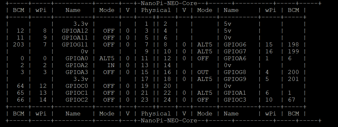
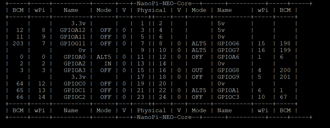
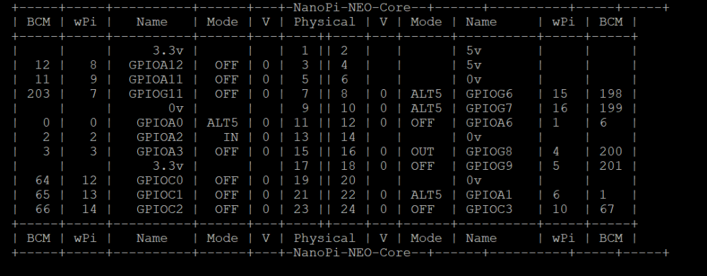
Hello guys, I am trying to use hardware flow control over the uart 1 of a nanopi neo core that I am using with a minishield. The GPIO pins of RX,TX,RTS and CTS of uart 1 based on this documentation (http://wiki.friendlyarm.com/wiki/index.php/Mini_Shield_for_NanoPi_NEO_Core/Core2) are G6,G7,G8 and G9. First of all I downloaded WiringNP in order to see the status of each GPIO. Before activating the rts cts on uart1, the figure "beforeActivatingRTSCTS" is the output of the command "gpio readall" . Then I added to the /boot/armbianEnv.txt the following overlay : param_uart1_rtscts=1 I rebooted the nanopi. After reboot, the figure "AfterActivatingRTSCTS" is the output of the command "gpio readall". As you can see, the GPIOG9 switched to ALT5 but GPIOG8 stayed the same. I am supposing that the ALT5 is the Alternate function for RTS CTS. Is that right? Why the GPIOG8 didn't change to ALT5 after activating the RTS CTS ? Is there something that I am doing wrong to activate these pins? Do I need to instruct the serial port driver to use the hardware flow control signals? Thanks in advance. Regards, Antony

-
HI, I have OrangePiPc and need to activate 3 uart (TX-RX) pins as system serial ports (/dev/ttyAMA0, /dev/ttyAMA1, /dev/ttyAMA2) how do it?
-
Hi all, I've pre-ordered my helios4 and was so excited to finally receive my new NAS after a few months of waiting. I love this project and want to see this project to grow and maybe inspire others to create similar projects as this one. That said, I was really disappointed when I finally started my board and realized that the UART to micro usb was broken when I plugged it in my computer. No USB device is at all recognized(on linux nor on my mac). At first, to eliminate any potential problems, I tried at least 6 different micro usb to usb cables thinking that a cable could be broken... it happens some time. With all 6 cables tried, never did I get my computer to detect a USB device plugged in. To continue my great adventure, I soldered a 3 pin header on the UART ports of the board since I have a UART to USB cable at home. Once the pins were soldered on the board, with great excitement I booted the puppy to see if it fixed my issue. It fixed only half the issue. I now detect the USB device andI can now see all tx leaving the arm board however the rx seems to be broken. I get to the login page but can't type anything. Well that sucks. I was hoping the issue was between the UART and micro USB controller but I was wrong. Maybe the issue was with the rx all along and the UART to USB controller just don't work when either rx or tx is not working(this is just a guess). The issue is now more uphill than I thought and I won't be able to troubleshoot this on my own since I am no electronic engineer. So now, I have a brand new board but with only tx working but not rx so basically I am at a loss here. This looks like a manufacturing issue. Am I the only one who has this problem? This is part of batch 3 helio4. Please let me know if you ever went through something similar or if you have an idea how I can fix this. Any help would be appreciated and if others from the same batch has this issue, it would be great to report it rather to leave it at a loss. Thanks
-
Previously running a different Linux, I followed the instructions to update the boot loader so I could try Armbian on my Espressobin. The update completed ok, but could no longer read from the SD card. After several hours of frustration, I attempted to revert back to the original boot loader and found I could no longer tftp or update from USB. After several days of frustration, I am near the point of giving up. Here's what happens when I attempt to use the UART rescue found at the Espressobin web site: Marvell>> usb start starting USB... USB0: Register 2000104 NbrPorts 2 Starting the controller USB XHCI 1.00 USB1: USB EHCI 1.00 scanning bus 0 for devices... 2 USB Device(s) found scanning bus 1 for devices... 1 USB Device(s) found scanning usb for storage devices... 1 Storage Device(s) found Marvell>> bubt bootloader.bin spi usb Burning U-BOOT image "bootloader.bin" from "usb" to "spi" USB0: Register 2000104 NbrPorts 2 Starting the controller USB XHCI 1.00 USB1: USB EHCI 1.00 scanning bus 0 for devices... 2 USB Device(s) found scanning bus 1 for devices... 1 USB Device(s) found Image checksum...OK! SF: unrecognized JEDEC id bytes: c2, 25, 36 Failed to probe SPI Flash exit not allowed from main input shell. Marvell>> I then tried various newer UART rescue images, which all seem to recognize the SPI flash chip but cannot update from USB (yes, I tried various working USB memory sticks...): Marvell>> usb start starting USB... USB0: Register 2000104 NbrPorts 2 Starting the controller USB XHCI 1.00 USB1: USB EHCI 1.00 scanning bus 0 for devices... 2 USB Device(s) found scanning bus 1 for devices... 1 USB Device(s) found scanning usb for storage devices... 1 Storage Device(s) found Marvell>> bubt bootloader.bin spi usb Burning U-BOOT image "bootloader.bin" from "usb" to "spi" USB0: Register 2000104 NbrPorts 2 Starting the controller USB XHCI 1.00 USB1: USB EHCI 1.00 scanning bus 0 for devices... 2 USB Device(s) found scanning bus 1 for devices... 1 USB Device(s) found BUG: failure at drivers/usb/host/xhci-ring.c:489/abort_td()! BUG! resetting ... > I also tried updating via TFTP. All the UART rescue images I tried give the same result: tftp hangs, like this: Marvell>> setenv serverip 192.168.1.15 Marvell>> setenv ipaddr 192.168.1.12 Marvell>> ping $serverip Using neta@30000 device host 192.168.1.15 is alive Marvell>> bubt bootloader.bin spi tftp Burning U-BOOT image "bootloader.bin" from "tftp" to "spi" Using neta@30000 device TFTP from server 192.168.1.15; our IP address is 192.168.1.12 Filename 'bootloader.bin'. Load address: 0x80000000 Loading: # Has anyone else experienced this problem? I find it hard to believe the board is broken, since it was working fine prior to the first boot loader update.
-
Hi, I've got an Orange Pi Zero Plus H5 running "Armbian_5.91_Orangepizeroplus_Debian_buster_next_4.19.59.img" but I can't seem to connect to it via the three UART pins next to the Ethernet port. I'm using this adapter using both the Windows supplied and the manifacturer's drivers. I've also tried adding "uart1 uart2 uart3" to the overlays line in /boot/armbianEnv.txt and rebooting but with no luck. I'm using PuTTY on my laptop connecting via COM7 serial port (as shown in Device Manager) with baud rate 115200, but the PuTTY screen stays black with nothing coming in. Is there something that I'm missing?
-
hello I have a module of teleinformation on my GPIO port which must work on the UART 3 but I do not know at all how to configure it and it does not work, could you help me? I am under armbian 5.90. here is the link to my telinformation module: PiTinfo thank you in advance for your help
-
Hi, tell me please how to properly enable RUART (S-UART) on Orange Pi 3. The Armbian Bionic build (kernel 5.1) is installed, RUART (S-UART) is enabled via raspbian-config, but does not work. What are the options? Required to connect the UART device. UART 3 is working, RUART (S-UART) does not work. Image: Pin (08, 10)
-
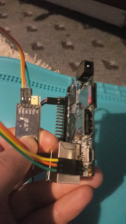
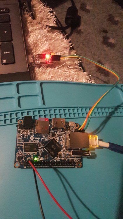
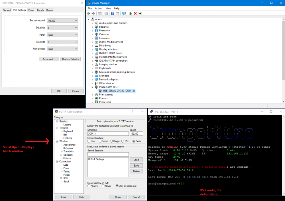
Hi, I'm new to the Armbian/Alt PI scene, coming from a RPI Zero W. I'm needing to interact with my PI using a CH340G (is it compatible) USB to TTL dongle. I've also trjed a CH351A device, put it into UART mode. Unfortunately, I get nothing from the PI. Despite using the primary RX/TX pins. I've also tried enabling all of the UART pins using armbian-config, and using another set of pins - to no avail. Please view my setup below. I've run out of ideas of where I'm going wrong. I've tried these images: Armbian_5.90_Nanopineo2_Debian_buster_next_4.19.57 Armbian_5.90_Orangepione_Ubuntu_bionic_next_4.19.57 Reference: http://linux-sunxi.org/File:Orange_Pi_One_UART.jpg