Search the Community
Showing results for 'gpio'.
-
 Two days ago I upgraded the kernel to 25.5.1 (6.12.30-current-sunxi) from 25.2.3 (6.12.20-current-sunxi). Since then I have no longer been able to play a certain title (FLAC file) in mocp. In case it's relevant, the title is: "Malukah - Awake (The Dragonborn Comes)". Symptoms: dmesg starts showing kernel trace output at 1:43 of the song mocp finally stalls at 1:52 and it's impossible to interact with it from that point on Is there anyone here who would be able to provide pointers on how to debug this? I am a developer and I have done some work with Yocto/OE before and wouldn't be afraid to get at this with a debugger. Since it's nicely reproducible, I could switch between those package versions to investigate. From the trace output it looks as if this is in exfat code. Makes sense, since the song is getting played from a USB key that is exfat-formatted. Here's the dmesg output with the two traces towards the end. I decided to include a few messages up to the point where systemd starts: [ 0.000000] Booting Linux on physical CPU 0x0 [ 0.000000] Linux version 6.12.30-current-sunxi (build@armbian) (arm-linux-gnueabihf-gcc (Ubuntu 13.2.0-23ubuntu4) 13.2.0, GNU ld (GNU Binutils for Ubuntu) 2.42) #1 SMP Thu May 22 12:29:54 UTC 2025 [ 0.000000] CPU: ARMv7 Processor [410fc074] revision 4 (ARMv7), cr=50c5387d [ 0.000000] CPU: div instructions available: patching division code [ 0.000000] CPU: PIPT / VIPT nonaliasing data cache, VIPT aliasing instruction cache [ 0.000000] OF: fdt: Machine model: Cubietech Cubietruck [ 0.000000] Memory policy: Data cache writealloc [ 0.000000] Reserved memory: created CMA memory pool at 0x4a000000, size 96 MiB [ 0.000000] OF: reserved mem: initialized node default-pool, compatible id shared-dma-pool [ 0.000000] OF: reserved mem: 0x4a000000..0x4fffffff (98304 KiB) map reusable default-pool [ 0.000000] Zone ranges: [ 0.000000] Normal [mem 0x0000000040000000-0x000000006fffffff] [ 0.000000] HighMem [mem 0x0000000070000000-0x00000000bfcfffff] [ 0.000000] Movable zone start for each node [ 0.000000] Early memory node ranges [ 0.000000] node 0: [mem 0x0000000040000000-0x00000000bfcfffff] [ 0.000000] Initmem setup node 0 [mem 0x0000000040000000-0x00000000bfcfffff] [ 0.000000] On node 0, zone HighMem: 768 pages in unavailable ranges [ 0.000000] psci: probing for conduit method from DT. [ 0.000000] psci: Using PSCI v0.1 Function IDs from DT [ 0.000000] percpu: Embedded 19 pages/cpu s48588 r8192 d21044 u77824 [ 0.000000] pcpu-alloc: s48588 r8192 d21044 u77824 alloc=19*4096 [ 0.000000] pcpu-alloc: [0] 0 [0] 1 [ 0.000000] Kernel command line: root=UUID=ad99c006-e2fa-4070-8fbe-9e08f643dd62 rootwait rootfstype=ext4 console=ttyS0,115200 console=tty1 hdmi.audio=EDID:0 disp.screen0_output_mode=1920x1080p60 consoleblank=0 loglevel=1 ubootpart=5b507211-01 ubootsource=mmc usb-storage.quirks=0x2537:0x1066:u,0x2537:0x1068:u sunxi_ve_mem_reserve=0 sunxi_g2d_mem_reserve=0 sunxi_fb_mem_reserve=16 cgroup_enable=memory swapaccount=1 [ 0.000000] Unknown kernel command line parameters "ubootpart=5b507211-01 ubootsource=mmc sunxi_ve_mem_reserve=0 sunxi_g2d_mem_reserve=0 sunxi_fb_mem_reserve=16 cgroup_enable=memory", will be passed to user space. [ 0.000000] Dentry cache hash table entries: 131072 (order: 7, 524288 bytes, linear) [ 0.000000] Inode-cache hash table entries: 65536 (order: 6, 262144 bytes, linear) [ 0.000000] Built 1 zonelists, mobility grouping on. Total pages: 523520 [ 0.000000] mem auto-init: stack:all(zero), heap alloc:on, heap free:off [ 0.000000] SLUB: HWalign=64, Order=0-3, MinObjects=0, CPUs=2, Nodes=1 [ 0.000000] allocated 2097152 bytes of page_ext [ 0.000000] ftrace: allocating 47264 entries in 139 pages [ 0.000000] ftrace: allocated 139 pages with 4 groups [ 0.000000] rcu: Hierarchical RCU implementation. [ 0.000000] rcu: RCU restricting CPUs from NR_CPUS=8 to nr_cpu_ids=2. [ 0.000000] Rude variant of Tasks RCU enabled. [ 0.000000] Tracing variant of Tasks RCU enabled. [ 0.000000] rcu: RCU calculated value of scheduler-enlistment delay is 25 jiffies. [ 0.000000] rcu: Adjusting geometry for rcu_fanout_leaf=16, nr_cpu_ids=2 [ 0.000000] RCU Tasks Rude: Setting shift to 1 and lim to 1 rcu_task_cb_adjust=1 rcu_task_cpu_ids=2. [ 0.000000] RCU Tasks Trace: Setting shift to 1 and lim to 1 rcu_task_cb_adjust=1 rcu_task_cpu_ids=2. [ 0.000000] NR_IRQS: 16, nr_irqs: 16, preallocated irqs: 16 [ 0.000000] GIC: Using split EOI/Deactivate mode [ 0.000000] rcu: srcu_init: Setting srcu_struct sizes based on contention. [ 0.000000] arch_timer: cp15 timer(s) running at 24.00MHz (phys). [ 0.000000] clocksource: arch_sys_counter: mask: 0xffffffffffffff max_cycles: 0x588fe9dc0, max_idle_ns: 440795202592 ns [ 0.000002] sched_clock: 56 bits at 24MHz, resolution 41ns, wraps every 4398046511097ns [ 0.000018] Switching to timer-based delay loop, resolution 41ns [ 0.000435] clocksource: timer: mask: 0xffffffff max_cycles: 0xffffffff, max_idle_ns: 79635851949 ns [ 0.001281] Console: colour dummy device 80x30 [ 0.001311] printk: legacy console [tty1] enabled [ 0.001505] Calibrating delay loop (skipped), value calculated using timer frequency.. 48.00 BogoMIPS (lpj=96000) [ 0.001530] CPU: Testing write buffer coherency: ok [ 0.001607] pid_max: default: 32768 minimum: 301 [ 0.010543] LSM: initializing lsm=capability,yama,apparmor [ 0.013707] Yama: becoming mindful. [ 0.014095] AppArmor: AppArmor initialized [ 0.015557] Mount-cache hash table entries: 2048 (order: 1, 8192 bytes, linear) [ 0.015592] Mountpoint-cache hash table entries: 2048 (order: 1, 8192 bytes, linear) [ 0.021695] CPU0: thread -1, cpu 0, socket 0, mpidr 80000000 [ 0.044852] Setting up static identity map for 0x40100000 - 0x40100054 [ 0.048263] rcu: Hierarchical SRCU implementation. [ 0.048283] rcu: Max phase no-delay instances is 1000. [ 0.048858] Timer migration: 1 hierarchy levels; 8 children per group; 1 crossnode level [ 0.054065] smp: Bringing up secondary CPUs ... [ 0.071012] CPU1: thread -1, cpu 1, socket 0, mpidr 80000001 [ 0.071303] smp: Brought up 1 node, 2 CPUs [ 0.071330] SMP: Total of 2 processors activated (96.00 BogoMIPS). [ 0.071345] CPU: All CPU(s) started in HYP mode. [ 0.071352] CPU: Virtualization extensions available. [ 0.071568] Memory: 1933492K/2094080K available (10240K kernel code, 1685K rwdata, 9100K rodata, 1024K init, 409K bss, 57468K reserved, 98304K cma-reserved, 1307648K highmem) [ 0.073644] devtmpfs: initialized [ 0.086909] VFP support v0.3: implementor 41 architecture 2 part 30 variant 7 rev 4 [ 0.087516] clocksource: jiffies: mask: 0xffffffff max_cycles: 0xffffffff, max_idle_ns: 7645041785100000 ns [ 0.087579] futex hash table entries: 512 (order: 3, 32768 bytes, linear) [ 0.096245] pinctrl core: initialized pinctrl subsystem [ 0.099654] NET: Registered PF_NETLINK/PF_ROUTE protocol family [ 0.107107] DMA: preallocated 256 KiB pool for atomic coherent allocations [ 0.108097] audit: initializing netlink subsys (disabled) [ 0.108752] audit: type=2000 audit(0.100:1): state=initialized audit_enabled=0 res=1 [ 0.109807] thermal_sys: Registered thermal governor 'fair_share' [ 0.109827] thermal_sys: Registered thermal governor 'bang_bang' [ 0.109838] thermal_sys: Registered thermal governor 'step_wise' [ 0.110006] cpuidle: using governor ladder [ 0.110071] cpuidle: using governor menu [ 0.110879] hw-breakpoint: found 5 (+1 reserved) breakpoint and 4 watchpoint registers. [ 0.110905] hw-breakpoint: maximum watchpoint size is 8 bytes. [ 0.121698] /soc/lcd-controller@1c0c000: Fixed dependency cycle(s) with /soc/hdmi@1c16000 [ 0.121833] /soc/lcd-controller@1c0c000: Fixed dependency cycle(s) with /soc/display-backend@1e40000 [ 0.121937] /soc/lcd-controller@1c0c000: Fixed dependency cycle(s) with /soc/display-backend@1e60000 [ 0.122055] /soc/lcd-controller@1c0d000: Fixed dependency cycle(s) with /soc/hdmi@1c16000 [ 0.122158] /soc/lcd-controller@1c0d000: Fixed dependency cycle(s) with /soc/display-backend@1e40000 [ 0.122261] /soc/lcd-controller@1c0d000: Fixed dependency cycle(s) with /soc/display-backend@1e60000 [ 0.122578] /soc/hdmi@1c16000: Fixed dependency cycle(s) with /soc/lcd-controller@1c0d000 [ 0.122732] /soc/hdmi@1c16000: Fixed dependency cycle(s) with /soc/lcd-controller@1c0c000 [ 0.123085] /soc/interrupt-controller@1c81000: Fixed dependency cycle(s) with /soc/interrupt-controller@1c81000 [ 0.123248] /soc/display-frontend@1e00000: Fixed dependency cycle(s) with /soc/display-backend@1e40000 [ 0.123439] /soc/display-frontend@1e00000: Fixed dependency cycle(s) with /soc/display-backend@1e60000 [ 0.123615] /soc/display-frontend@1e20000: Fixed dependency cycle(s) with /soc/display-backend@1e40000 [ 0.123773] /soc/display-frontend@1e20000: Fixed dependency cycle(s) with /soc/display-backend@1e60000 [ 0.123862] /soc/display-backend@1e40000: Fixed dependency cycle(s) with /soc/lcd-controller@1c0d000 [ 0.123940] /soc/display-backend@1e40000: Fixed dependency cycle(s) with /soc/lcd-controller@1c0c000 [ 0.124009] /soc/display-backend@1e40000: Fixed dependency cycle(s) with /soc/display-frontend@1e20000 [ 0.124077] /soc/display-backend@1e40000: Fixed dependency cycle(s) with /soc/display-frontend@1e00000 [ 0.124170] /soc/display-backend@1e60000: Fixed dependency cycle(s) with /soc/lcd-controller@1c0d000 [ 0.124249] /soc/display-backend@1e60000: Fixed dependency cycle(s) with /soc/lcd-controller@1c0c000 [ 0.124317] /soc/display-backend@1e60000: Fixed dependency cycle(s) with /soc/display-frontend@1e20000 [ 0.124386] /soc/display-backend@1e60000: Fixed dependency cycle(s) with /soc/display-frontend@1e00000 [ 0.125215] /soc/lcd-controller@1c0c000: Fixed dependency cycle(s) with /soc/hdmi@1c16000 [ 0.125339] /soc/lcd-controller@1c0c000: Fixed dependency cycle(s) with /soc/display-backend@1e40000 [ 0.125455] /soc/lcd-controller@1c0c000: Fixed dependency cycle(s) with /soc/display-backend@1e60000 [ 0.125804] /soc/lcd-controller@1c0d000: Fixed dependency cycle(s) with /soc/hdmi@1c16000 [ 0.125918] /soc/lcd-controller@1c0d000: Fixed dependency cycle(s) with /soc/display-backend@1e40000 [ 0.126030] /soc/lcd-controller@1c0d000: Fixed dependency cycle(s) with /soc/display-backend@1e60000 [ 0.128237] /soc/lcd-controller@1c0d000: Fixed dependency cycle(s) with /soc/hdmi@1c16000 [ 0.128436] /soc/lcd-controller@1c0c000: Fixed dependency cycle(s) with /soc/hdmi@1c16000 [ 0.128705] /soc/hdmi@1c16000: Fixed dependency cycle(s) with /soc/lcd-controller@1c0d000 [ 0.128943] /soc/hdmi@1c16000: Fixed dependency cycle(s) with /soc/lcd-controller@1c0c000 [ 0.131769] /soc/pinctrl@1c20800: Fixed dependency cycle(s) with /soc/pinctrl@1c20800/clk-out-a-pin [ 0.136344] /soc/display-frontend@1e00000: Fixed dependency cycle(s) with /soc/display-backend@1e40000 [ 0.136455] /soc/display-frontend@1e00000: Fixed dependency cycle(s) with /soc/display-backend@1e60000 [ 0.136830] /soc/display-frontend@1e20000: Fixed dependency cycle(s) with /soc/display-backend@1e40000 [ 0.136924] /soc/display-frontend@1e20000: Fixed dependency cycle(s) with /soc/display-backend@1e60000 [ 0.137304] /soc/display-frontend@1e20000: Fixed dependency cycle(s) with /soc/display-backend@1e40000 [ 0.137470] /soc/display-frontend@1e00000: Fixed dependency cycle(s) with /soc/display-backend@1e40000 [ 0.137604] /soc/lcd-controller@1c0d000: Fixed dependency cycle(s) with /soc/display-backend@1e40000 [ 0.137736] /soc/lcd-controller@1c0c000: Fixed dependency cycle(s) with /soc/display-backend@1e40000 [ 0.137883] /soc/display-backend@1e40000: Fixed dependency cycle(s) with /soc/lcd-controller@1c0d000 [ 0.138028] /soc/display-backend@1e40000: Fixed dependency cycle(s) with /soc/lcd-controller@1c0c000 [ 0.138142] /soc/display-backend@1e40000: Fixed dependency cycle(s) with /soc/display-frontend@1e20000 [ 0.138279] /soc/display-backend@1e40000: Fixed dependency cycle(s) with /soc/display-frontend@1e00000 [ 0.138694] /soc/display-frontend@1e20000: Fixed dependency cycle(s) with /soc/display-backend@1e60000 [ 0.138884] /soc/display-frontend@1e00000: Fixed dependency cycle(s) with /soc/display-backend@1e60000 [ 0.139055] /soc/lcd-controller@1c0d000: Fixed dependency cycle(s) with /soc/display-backend@1e60000 [ 0.139186] /soc/lcd-controller@1c0c000: Fixed dependency cycle(s) with /soc/display-backend@1e60000 [ 0.139302] /soc/display-backend@1e60000: Fixed dependency cycle(s) with /soc/lcd-controller@1c0d000 [ 0.139477] /soc/display-backend@1e60000: Fixed dependency cycle(s) with /soc/lcd-controller@1c0c000 [ 0.139661] /soc/display-backend@1e60000: Fixed dependency cycle(s) with /soc/display-frontend@1e20000 [ 0.139780] /soc/display-backend@1e60000: Fixed dependency cycle(s) with /soc/display-frontend@1e00000 [ 0.142414] /soc/hdmi@1c16000: Fixed dependency cycle(s) with /hdmi-connector [ 0.142644] /hdmi-connector: Fixed dependency cycle(s) with /soc/hdmi@1c16000 [ 0.154682] cryptd: max_cpu_qlen set to 1000 [ 0.232124] raid6: neonx8 gen() 582 MB/s [ 0.300278] raid6: neonx4 gen() 822 MB/s [ 0.368453] raid6: neonx2 gen() 825 MB/s [ 0.436671] raid6: neonx1 gen() 677 MB/s [ 0.504833] raid6: int32x8 gen() 252 MB/s [ 0.572914] raid6: int32x4 gen() 289 MB/s [ 0.641009] raid6: int32x2 gen() 365 MB/s [ 0.709128] raid6: int32x1 gen() 337 MB/s [ 0.709142] raid6: using algorithm neonx2 gen() 825 MB/s [ 0.777211] raid6: .... xor() 614 MB/s, rmw enabled [ 0.777223] raid6: using neon recovery algorithm [ 0.779037] iommu: Default domain type: Translated [ 0.779063] iommu: DMA domain TLB invalidation policy: strict mode [ 0.780359] SCSI subsystem initialized [ 0.780941] libata version 3.00 loaded. [ 0.781297] usbcore: registered new interface driver usbfs [ 0.781366] usbcore: registered new interface driver hub [ 0.781432] usbcore: registered new device driver usb [ 0.781783] pps_core: LinuxPPS API ver. 1 registered [ 0.781798] pps_core: Software ver. 5.3.6 - Copyright 2005-2007 Rodolfo Giometti <giometti@linux.it> [ 0.781825] PTP clock support registered [ 0.782595] Advanced Linux Sound Architecture Driver Initialized. [ 0.784208] NetLabel: Initializing [ 0.784231] NetLabel: domain hash size = 128 [ 0.784242] NetLabel: protocols = UNLABELED CIPSOv4 CALIPSO [ 0.784360] NetLabel: unlabeled traffic allowed by default [ 0.785656] clocksource: Switched to clocksource arch_sys_counter [ 0.798624] VFS: Disk quotas dquot_6.6.0 [ 0.798981] VFS: Dquot-cache hash table entries: 1024 (order 0, 4096 bytes) [ 0.799863] AppArmor: AppArmor Filesystem Enabled [ 0.816412] NET: Registered PF_INET protocol family [ 0.816787] IP idents hash table entries: 16384 (order: 5, 131072 bytes, linear) [ 0.903926] tcp_listen_portaddr_hash hash table entries: 512 (order: 0, 4096 bytes, linear) [ 0.904136] Table-perturb hash table entries: 65536 (order: 6, 262144 bytes, linear) [ 0.904189] TCP established hash table entries: 8192 (order: 3, 32768 bytes, linear) [ 0.904385] TCP bind hash table entries: 8192 (order: 5, 131072 bytes, linear) [ 0.904778] TCP: Hash tables configured (established 8192 bind 8192) [ 0.905038] UDP hash table entries: 512 (order: 2, 16384 bytes, linear) [ 0.905134] UDP-Lite hash table entries: 512 (order: 2, 16384 bytes, linear) [ 0.906025] NET: Registered PF_UNIX/PF_LOCAL protocol family [ 0.906649] Trying to unpack rootfs image as initramfs... [ 0.910989] Initialise system trusted keyrings [ 0.911155] Key type blacklist registered [ 0.912237] workingset: timestamp_bits=14 max_order=19 bucket_order=5 [ 0.912442] zbud: loaded [ 0.915119] squashfs: version 4.0 (2009/01/31) Phillip Lougher [ 0.926275] fuse: init (API version 7.41) [ 0.942065] integrity: Platform Keyring initialized [ 0.942166] xor: measuring software checksum speed [ 0.945010] arm4regs : 1159 MB/sec [ 0.950057] 8regs : 656 MB/sec [ 0.954923] 32regs : 680 MB/sec [ 0.957769] neon : 1170 MB/sec [ 0.957807] xor: using function: neon (1170 MB/sec) [ 0.957845] Key type asymmetric registered [ 0.957862] Asymmetric key parser 'x509' registered [ 0.958690] bounce: pool size: 64 pages [ 0.959359] Block layer SCSI generic (bsg) driver version 0.4 loaded (major 247) [ 0.960113] io scheduler mq-deadline registered [ 0.960146] io scheduler kyber registered [ 0.960735] io scheduler bfq registered [ 0.977058] ledtrig-cpu: registered to indicate activity on CPUs [ 0.995929] Serial: 8250/16550 driver, 8 ports, IRQ sharing disabled [ 1.014369] sun4i-drm display-engine: bound 1e00000.display-frontend (ops 0xc0bb0c8c) [ 1.014715] sun4i-drm display-engine: bound 1e20000.display-frontend (ops 0xc0bb0c8c) [ 1.015235] sun4i-drm display-engine: bound 1e60000.display-backend (ops 0xc0bb03f8) [ 1.015729] sun4i-drm display-engine: bound 1e40000.display-backend (ops 0xc0bb03f8) [ 1.016653] sun4i-drm display-engine: No panel or bridge found... RGB output disabled [ 1.016699] sun4i-drm display-engine: bound 1c0c000.lcd-controller (ops 0xc0bae8e8) [ 1.017975] sun4i-drm display-engine: No panel or bridge found... RGB output disabled [ 1.018031] sun4i-drm display-engine: bound 1c0d000.lcd-controller (ops 0xc0bae8e8) [ 1.020256] sun4i-drm display-engine: bound 1c16000.hdmi (ops 0xc0bb1688) [ 1.022796] [drm] Initialized sun4i-drm 1.0.0 for display-engine on minor 0 [ 1.022975] sun4i-drm display-engine: [drm] Cannot find any crtc or sizes [ 1.032968] brd: module loaded [ 1.039581] sun4i-drm display-engine: [drm] Cannot find any crtc or sizes [ 1.047130] loop: module loaded [ 1.055585] usbcore: registered new interface driver usb-storage [ 1.057950] sunxi-rtc 1c20d00.rtc: registered as rtc0 [ 1.058027] sunxi-rtc 1c20d00.rtc: setting system clock to 2025-07-02T08:56:46 UTC (1751446606) [ 1.058332] i2c_dev: i2c /dev entries driver [ 1.062076] sunxi-wdt 1c20c90.watchdog: Watchdog enabled (timeout=16 sec, nowayout=0) [ 1.064151] sun4i-ss 1c15000.crypto-engine: no reset control found [ 1.064308] sun4i-ss 1c15000.crypto-engine: Die ID 0 [ 1.066426] clocksource: hstimer: mask: 0xffffffff max_cycles: 0xffffffff, max_idle_ns: 6370868154 ns [ 1.066943] hid: raw HID events driver (C) Jiri Kosina [ 1.067216] usbcore: registered new interface driver usbhid [ 1.067237] usbhid: USB HID core driver [ 1.067954] armv7-pmu pmu: hw perfevents: no interrupt-affinity property, guessing. [ 1.071446] hw perfevents: enabled with armv7_cortex_a7 PMU driver, 5 (8000000f) counters available [ 1.095873] NET: Registered PF_INET6 protocol family [ 2.127070] Freeing initrd memory: 13656K [ 2.182392] Segment Routing with IPv6 [ 2.182617] In-situ OAM (IOAM) with IPv6 [ 2.182903] NET: Registered PF_PACKET protocol family [ 2.182935] NET: Registered PF_KEY protocol family [ 2.182985] bridge: filtering via arp/ip/ip6tables is no longer available by default. Update your scripts to load br_netfilter if you need this. [ 2.183410] Key type dns_resolver registered [ 2.184170] Registering SWP/SWPB emulation handler [ 2.196828] registered taskstats version 1 [ 2.197160] Loading compiled-in X.509 certificates [ 2.214355] zswap: loaded using pool zstd/zbud [ 2.215911] Key type .fscrypt registered [ 2.215942] Key type fscrypt-provisioning registered [ 2.226935] Btrfs loaded, zoned=no, fsverity=yes [ 2.307518] Key type encrypted registered [ 2.307567] AppArmor: AppArmor sha256 policy hashing enabled [ 2.328245] sun4i-pinctrl 1c20800.pinctrl: supply vcc-pi not found, using dummy regulator [ 2.328719] gpio gpiochip0: Static allocation of GPIO base is deprecated, use dynamic allocation. [ 2.331261] sun4i-pinctrl 1c20800.pinctrl: initialized sunXi PIO driver [ 2.332777] sun4i-pinctrl 1c20800.pinctrl: supply vcc-ph not found, using dummy regulator [ 2.336072] sun4i-pinctrl 1c20800.pinctrl: supply vcc-pb not found, using dummy regulator [ 2.337794] printk: legacy console [ttyS0] disabled [ 2.338531] 1c28000.serial: ttyS0 at MMIO 0x1c28000 (irq = 71, base_baud = 1500000) is a 16550A [ 2.338635] printk: legacy console [ttyS0] enabled [ 2.343112] 1c28800.serial: ttyS2 at MMIO 0x1c28800 (irq = 72, base_baud = 1500000) is a 16550A [ 2.343750] serial serial0: tty port ttyS2 registered [ 2.345203] sun4i-pinctrl 1c20800.pinctrl: supply vcc-pa not found, using dummy regulator [ 2.345901] sun7i-dwmac 1c50000.ethernet: IRQ eth_wake_irq not found [ 2.345938] sun7i-dwmac 1c50000.ethernet: IRQ eth_lpi not found [ 2.345954] sun7i-dwmac 1c50000.ethernet: IRQ sfty not found [ 2.346126] sun7i-dwmac 1c50000.ethernet: PTP uses main clock [ 2.346202] sun7i-dwmac 1c50000.ethernet: no regulator found [ 2.346880] sun7i-dwmac 1c50000.ethernet: Version ID not available [ 2.346924] sun7i-dwmac 1c50000.ethernet: DWMAC1000 [ 2.346940] sun7i-dwmac 1c50000.ethernet: No HW DMA feature register supported [ 2.346954] sun7i-dwmac 1c50000.ethernet: TX Checksum insertion supported [ 2.346969] sun7i-dwmac 1c50000.ethernet: Normal descriptors [ 2.346982] sun7i-dwmac 1c50000.ethernet: Ring mode enabled [ 2.378420] axp20x-i2c 1-0034: AXP20x variant AXP209 found [ 2.394479] input: axp20x-pek as /devices/platform/soc/1c2ac00.i2c/i2c-1/1-0034/axp20x-pek/input/input0 [ 2.400618] axp20x-i2c 1-0034: Backup (RTC) battery charging is disabled [ 2.400815] axp20x-i2c 1-0034: AXP20X driver loaded [ 2.406857] sun4i-pinctrl 1c20800.pinctrl: supply vcc-pf not found, using dummy regulator [ 2.413840] sunxi-mmc 1c0f000.mmc: Got CD GPIO [ 2.418221] ahci-sunxi 1c18000.sata: supply ahci not found, using dummy regulator [ 2.418494] ahci-sunxi 1c18000.sata: supply phy not found, using dummy regulator [ 2.438244] sunxi-mmc 1c0f000.mmc: initialized, max. request size: 16384 KB [ 2.465843] ahci-sunxi 1c18000.sata: controller can't do PMP, turning off CAP_PMP [ 2.465933] ahci-sunxi 1c18000.sata: SSS flag set, parallel bus scan disabled [ 2.465982] ahci-sunxi 1c18000.sata: AHCI vers 0001.0100, 32 command slots, 3 Gbps, platform mode [ 2.466005] ahci-sunxi 1c18000.sata: 1/1 ports implemented (port mask 0x1) [ 2.466021] ahci-sunxi 1c18000.sata: flags: ncq sntf stag pm led clo only pio slum part ccc [ 2.468318] scsi host0: ahci-sunxi [ 2.469308] ata1: SATA max UDMA/133 mmio [mem 0x01c18000-0x01c18fff] port 0x100 irq 119 lpm-pol 0 [ 2.474777] of_cfs_init [ 2.474978] of_cfs_init: OK [ 2.478704] mmc0: host does not support reading read-only switch, assuming write-enable [ 2.480932] mmc0: new high speed SDHC card at address b368 [ 2.484061] mmcblk0: mmc0:b368 NCard 3.70 GiB [ 2.713012] clk: Disabling unused clocks [ 2.713235] PM: genpd: Disabling unused power domains [ 2.713266] ALSA device list: [ 2.713278] #0: sun4i-codec [ 2.713992] mmcblk0: p1 [ 2.780858] ata1: SATA link up 3.0 Gbps (SStatus 123 SControl 300) [ 2.782832] ata1.00: Model 'Samsung SSD 840 EVO 500GB', rev 'EXT0CB6Q', applying quirks: noncqtrim zeroaftertrim nodmalog [ 2.782904] ata1.00: supports DRM functions and may not be fully accessible [ 2.782919] ata1.00: ATA-9: Samsung SSD 840 EVO 500GB, EXT0CB6Q, max UDMA/133 [ 2.782939] ata1.00: 976773168 sectors, multi 1: LBA48 NCQ (depth 32) [ 2.783422] ata1.00: Features: Trust [ 2.783673] ata1.00: supports DRM functions and may not be fully accessible [ 2.784145] ata1.00: configured for UDMA/133 [ 2.785048] scsi 0:0:0:0: Direct-Access ATA Samsung SSD 840 CB6Q PQ: 0 ANSI: 5 [ 2.787212] sd 0:0:0:0: Attached scsi generic sg0 type 0 [ 2.787270] sd 0:0:0:0: [sda] 976773168 512-byte logical blocks: (500 GB/466 GiB) [ 2.787381] sd 0:0:0:0: [sda] Write Protect is off [ 2.787406] sd 0:0:0:0: [sda] Mode Sense: 00 3a 00 00 [ 2.787559] sd 0:0:0:0: [sda] Write cache: enabled, read cache: enabled, doesn't support DPO or FUA [ 2.787919] sd 0:0:0:0: [sda] Preferred minimum I/O size 512 bytes [ 2.806306] sda: sda1 sda2 sda3 [ 2.807527] sd 0:0:0:0: [sda] Attached SCSI disk [ 2.816074] Freeing unused kernel image (initmem) memory: 1024K [ 2.816726] Run /init as init process [ 2.816754] with arguments: [ 2.816773] /init [ 2.816784] with environment: [ 2.816794] HOME=/ [ 2.816805] TERM=linux [ 2.816815] ubootpart=5b507211-01 [ 2.816826] ubootsource=mmc [ 2.816837] sunxi_ve_mem_reserve=0 [ 2.816847] sunxi_g2d_mem_reserve=0 [ 2.816858] sunxi_fb_mem_reserve=16 [ 2.816869] cgroup_enable=memory [ 3.909998] sunxi-mmc 1c12000.mmc: allocated mmc-pwrseq [ 3.933806] sunxi-mmc 1c12000.mmc: initialized, max. request size: 16384 KB [ 4.061411] mmc1: new high speed SDIO card at address 0001 [ 4.211031] sun5i-a13-gpadc-iio: Failed to locate of_node [id: 0] [ 4.283436] sun7i-dwmac 1c50000.ethernet end0: renamed from eth0 [ 4.301983] axp20x-gpio axp20x-gpio: DMA mask not set [ 4.327476] axp20x-gpio axp20x-gpio: AXP209 pinctrl and GPIO driver loaded [ 4.355581] axp20x-battery-power-supply axp20x-battery-power-supply: DMA mask not set [ 4.371464] axp20x-usb-power-supply axp20x-usb-power-supply: DMA mask not set [ 5.873099] EXT4-fs (sda1): mounted filesystem ad99c006-e2fa-4070-8fbe-9e08f643dd62 ro with ordered data mode. Quota mode: none. [ 14.571324] platform sound: deferred probe pending: asoc-simple-card: parse error [ 14.571365] platform 1c13400.phy: deferred probe pending: platform: supplier axp20x-usb-power-supply not ready [ 14.571381] platform 1c13000.usb: deferred probe pending: platform: supplier 1c13400.phy not ready [ 14.571395] platform 1c14000.usb: deferred probe pending: platform: supplier 1c13400.phy not ready [ 14.571409] platform 1c1c000.usb: deferred probe pending: platform: supplier 1c13400.phy not ready [ 14.571422] platform 1c14400.usb: deferred probe pending: platform: supplier 1c13400.phy not ready [ 14.571436] platform 1c1c400.usb: deferred probe pending: platform: supplier 1c13400.phy not ready [ 14.571449] platform axp20x-battery-power-supply: deferred probe pending: (reason unknown) [ 14.571462] platform axp20x-usb-power-supply: deferred probe pending: (reason unknown) [ 17.843978] systemd[1]: Inserted module 'autofs4' [ 18.117493] systemd[1]: systemd 255.4-1ubuntu8.8 running in system mode (+PAM +AUDIT +SELINUX +APPARMOR +IMA +SMACK +SECCOMP +GCRYPT -GNUTLS +OPENSSL +ACL +BLKID +CURL +ELFUTILS +FIDO2 +IDN2 -IDN +IPTC +KMOD +LIBCRYPTSETUP +LIBFDISK +PCRE2 -PWQUALITY +P11KIT +QRENCODE +TPM2 +BZIP2 +LZ4 +XZ +ZLIB +ZSTD -BPF_FRAMEWORK -XKBCOMMON +UTMP +SYSVINIT default-hierarchy=unified) [ 18.117576] systemd[1]: Detected architecture arm. ... SNIP ... [90829.705266] 8<--- cut here --- [90829.708505] Unable to handle kernel NULL pointer dereference at virtual address 00000255 when write [90829.717695] [00000255] *pgd=00000000 [90829.721519] Internal error: Oops: 805 [#1] SMP THUMB2 [90829.726679] Modules linked in: nls_utf8 cifs cifs_arc4 nls_ucs2_utils cifs_md4 netfs exfat snd_usb_audio snd_hwdep binfmt_misc snd_seq_dummy snd_usbmidi_lib snd_seq_oss snd_seq_midi snd_seq_midi_event snd_seq snd_rawmidi snd_seq_device uas lima gpu_sched drm_shmem_helper axp20x_adc sunxi_cedrus(C) sun4i_gpadc_iio v4l2_mem2mem videobuf2_dma_contig videobuf2_memops videobuf2_v4l2 sunxi_cir videobuf2_common videodev mc display_connector cpufreq_dt evdev brcmfmac_wcc sch_fq_codel bonding brcmfmac brcmutil cfg80211 rfkill dm_mod autofs4 ext4 mbcache jbd2 axp20x_usb_power axp20x_battery industrialio pinctrl_axp209 sun4i_gpadc pwm_sun4i sunxi phy_generic uio_pdrv_genirq pwrseq_simple uio realtek [90829.788428] CPU: 1 UID: 1000 PID: 14406 Comm: mocp Tainted: G C 6.12.30-current-sunxi #1 [90829.797976] Tainted: [C]=CRAP [90829.800979] Hardware name: Allwinner sun7i (A20) Family [90829.806223] PC is at mmioset+0x90/0xa4 [90829.810015] LR is at exfat_get_block+0x58b/0x638 [exfat] [90829.815374] pc : [<c0ab76b0>] lr : [<bfbdf847>] psr: 8003b833 [90829.821651] sp : f2559b48 ip : 00000255 fp : 00000000 [90829.826890] r10: 00004931 r9 : 00926255 r8 : c5a21400 [90829.832128] r7 : d09bc5c0 r6 : 00000000 r5 : 00000200 r4 : 00000055 [90829.838668] r3 : 00000001 r2 : 000001a7 r1 : 00000000 r0 : 00000255 [90829.845209] Flags: Nzcv IRQs on FIQs on Mode SVC_32 ISA Thumb Segment none [90829.852537] Control: 50c5387d Table: 536e006a DAC: 00000051 [90829.858294] Register r0 information: non-paged memory [90829.863367] Register r1 information: NULL pointer [90829.868089] Register r2 information: non-paged memory [90829.873156] Register r3 information: non-paged memory [90829.878221] Register r4 information: non-paged memory [90829.883286] Register r5 information: non-paged memory [90829.888356] Register r6 information: NULL pointer [90829.893082] Register r7 information: slab buffer_head start d09bc5c0 pointer offset 0 size 64 [90829.901656] Register r8 information: slab kmalloc-1k start c5a21400 pointer offset 0 size 1024 [90829.910306] Register r9 information: non-paged memory [90829.915380] Register r10 information: non-paged memory [90829.920533] Register r11 information: NULL pointer [90829.925338] Register r12 information: non-paged memory [90829.930495] Process mocp (pid: 14406, stack limit = 0xfea269c0) [90829.936437] Stack: (0xf2559b48 to 0xf255a000) [90829.940814] 9b40: d09bc240 2e2746cd 00000001 d09bc5c0 00000000 c597c86c [90829.949011] 9b60: 00000001 00000024 c5a21400 00000000 c597c800 d09bc240 00000000 0012aace [90829.957211] 9b80: 0012aacd 00000000 00000000 00000000 00000000 2e2746cd 00000000 00004931 [90829.965406] 9ba0: d09bc5c0 00000000 00000001 00000200 e1bc1760 d09bc240 00000200 c032a52f [90829.973601] 9bc0: d09bc5c0 00000000 00000000 00004932 00000000 ef5b9864 bfbdf2bd 00000000 [90829.981796] 9be0: e5afa800 00000000 00000054 d09bc240 00000000 00000000 00000000 00000000 [90829.989993] 9c00: 00000000 00000000 00000000 2e2746cd 00afa800 e22e4a80 00000001 00000000 [90829.998200] 9c20: f2559c98 c2840400 00000008 00000008 00004932 c032c541 f2559cb0 00000000 [90830.006409] 9c40: 255febb0 00000009 00000000 00000000 ef5b9864 f2559cb0 e1bc1760 c2840400 [90830.014612] 9c60: 00000000 00000001 00012cc0 00080000 00260000 f2559dd4 ef5b9864 00000001 [90830.022812] 9c80: 00000001 0000000b 00112cca e1bc186c 0000091c c032cfb1 00000000 ef5b9864 [90830.031006] 9ca0: 00000001 00000001 255febaf 00000000 00000000 00000000 ef5b9864 00000000 [90830.039202] 9cc0: 255febb1 00000000 00000200 00000000 c2840400 00000000 00000000 00000000 [90830.047396] 9ce0: 00000000 00000000 00000000 00000000 000048e0 bfbdf2bd 00260000 2e2746cd [90830.055591] 9d00: bfb86090 f2559dd4 f2559dd4 c0286967 00000000 ef5b9864 00000000 00000000 [90830.063788] 9d20: 00000000 00000000 00000000 00000000 00000001 00000100 f2559d38 f2559d38 [90830.071985] 9d40: 00000000 2e2746cd 0000000a 0000000b e5afa800 f2559dd4 e1bc1878 c0286bc3 [90830.080182] 9d60: e5afa800 e1bc1868 ffffffeb 00400040 e1bc1878 e5afa800 e1bc1868 8c140000 [90830.088384] 9d80: f2559e4c e1bc1868 ef80aae4 e5afa800 000008fc f2559f28 000008fa c027dd25 [90830.096580] 9da0: e5afae4c ede0f780 ede0f7e8 000008fd f2559dec c15adf00 00000000 00000000 [90830.104777] 9dc0: 00001fa0 e5afa800 e5afa800 2e2746cd 00000000 ede0f780 e1bc1868 ede0f7e8 [90830.112973] 9de0: 00000926 00000001 00000001 00000000 00000000 2e2746cd 00000002 00926255 [90830.121170] 9e00: 00000004 008fabe0 00000000 e1bc1760 b117bb9c 00000001 f2559f28 c027dfc5 [90830.129370] 9e20: f2559f10 c0ae793f c250c988 00000000 e5afa800 c01b36e1 e5afa800 c01b3b53 [90830.137568] 9e40: e1bc1868 ede0f780 e5afa800 00000003 ef5b8cb8 ef80ab74 ef80aae4 00000000 [90830.145762] 9e60: 00000000 00000000 00000000 00000000 00000000 00000000 00000000 00000000 [90830.153960] 9e80: 00000000 00000000 00000000 00000000 00000000 00000000 00000000 00000000 [90830.162153] 9ea0: 00000000 00000000 00000000 00000000 00000000 00000000 00000000 00000000 [90830.170347] 9ec0: 00000000 00000000 00000000 2e2746cd e5afa800 bfbe6225 ede0f780 e5afa800 [90830.178542] 9ee0: 00001fa0 f2559f80 b117bb9c 00000001 bfb87c80 c02f0a13 00000000 00000002 [90830.186737] 9f00: 00000001 f2559f00 c265aa00 00000000 00000000 00000000 b117bb9c 00001fa0 [90830.194933] 9f20: 00000001 00000000 ede0f780 00000000 008fabe0 00000000 00000000 00000000 [90830.203129] 9f40: 00000000 00004004 00000000 00000000 b12007d4 2e2746cd b12007d4 ede0f783 [90830.211332] 9f60: ede0f780 008fabe0 00000000 c01002a0 e5afa800 00000003 b120076c c02f114b [90830.219536] 9f80: 008fabe0 00000000 c0102455 2e2746cd 00000001 00001fa0 b117bb9c 00000004 [90830.227731] 9fa0: 00000003 c0100061 00001fa0 b117bb9c 00000004 b117bb9c 00001fa0 00000000 [90830.235929] 9fc0: 00001fa0 b117bb9c 00000004 00000003 00001fa0 00001fa0 b12007f0 b120076c [90830.244122] 9fe0: 00000003 b117bad0 b6ac36d1 b6a396c6 80030030 00000004 00000000 00000000 [90830.252311] Call trace: [90830.252331] mmioset from exfat_get_block+0x58b/0x638 [exfat] [90830.260706] exfat_get_block [exfat] from block_read_full_folio+0xf7/0x2b0 [90830.267634] block_read_full_folio from do_mpage_readpage+0x71/0x498 [90830.274031] do_mpage_readpage from mpage_readahead+0x8d/0xe4 [90830.279818] mpage_readahead from read_pages+0x4b/0x1e8 [90830.285078] read_pages from page_cache_ra_unbounded+0xbf/0x12c [90830.291027] page_cache_ra_unbounded from filemap_get_pages+0x385/0x554 [90830.297674] filemap_get_pages from filemap_read+0xd1/0x34c [90830.303276] filemap_read from vfs_read+0x1b3/0x228 [90830.308191] vfs_read from ksys_read+0x53/0xa8 [90830.312668] ksys_read from ret_fast_syscall+0x1/0x5c [90830.317751] Exception stack(0xf2559fa8 to 0xf2559ff0) [90830.322822] 9fa0: 00001fa0 b117bb9c 00000004 b117bb9c 00001fa0 00000000 [90830.331019] 9fc0: 00001fa0 b117bb9c 00000004 00000003 00001fa0 00001fa0 b12007f0 b120076c [90830.339214] 9fe0: 00000003 b117bad0 b6ac36d1 b6a396c6 [90830.344288] Code: 3a04 dbf0 2b02 bfb8 (f80c) 1b01 [90830.349338] ---[ end trace 0000000000000000 ]--- [90830.354108] ------------[ cut here ]------------ [90830.358863] WARNING: CPU: 1 PID: 14406 at kernel/exit.c:886 do_exit+0x62d/0x744 [90830.366383] Modules linked in: nls_utf8 cifs cifs_arc4 nls_ucs2_utils cifs_md4 netfs exfat snd_usb_audio snd_hwdep binfmt_misc snd_seq_dummy snd_usbmidi_lib snd_seq_oss snd_seq_midi snd_seq_midi_event snd_seq snd_rawmidi snd_seq_device uas lima gpu_sched drm_shmem_helper axp20x_adc sunxi_cedrus(C) sun4i_gpadc_iio v4l2_mem2mem videobuf2_dma_contig videobuf2_memops videobuf2_v4l2 sunxi_cir videobuf2_common videodev mc display_connector cpufreq_dt evdev brcmfmac_wcc sch_fq_codel bonding brcmfmac brcmutil cfg80211 rfkill dm_mod autofs4 ext4 mbcache jbd2 axp20x_usb_power axp20x_battery industrialio pinctrl_axp209 sun4i_gpadc pwm_sun4i sunxi phy_generic uio_pdrv_genirq pwrseq_simple uio realtek [90830.427987] CPU: 1 UID: 1000 PID: 14406 Comm: mocp Tainted: G D C 6.12.30-current-sunxi #1 [90830.428023] Tainted: [D]=DIE, [C]=CRAP [90830.428029] Hardware name: Allwinner sun7i (A20) Family [90830.428036] Call trace: [90830.428050] unwind_backtrace from show_stack+0x11/0x14 [90830.428091] show_stack from dump_stack_lvl+0x37/0x42 [90830.428114] dump_stack_lvl from __warn+0xbf/0xe8 [90830.428138] __warn from warn_slowpath_fmt+0x113/0x118 [90830.428161] warn_slowpath_fmt from do_exit+0x62d/0x744 [90830.428186] do_exit from make_task_dead+0x77/0x11c [90830.428214] make_task_dead from die+0x2a5/0x364 [90830.428235] die from die_kernel_fault+0x6f/0x84 [90830.428258] die_kernel_fault from do_translation_fault+0x1/0x88 [90830.428283] do_translation_fault from 0xc160323c [90830.428338] ---[ end trace 0000000000000000 ]--- The issue is easy enough to work around, simply downgrade to the working version: # apt install linux-image-current-sunxi=25.2.3 armbian-firmware=25.2.3 linux-dtb-current-sunxi=25.2.3 Reading package lists... Done Building dependency tree... Done Reading state information... Done The following packages will be DOWNGRADED: armbian-firmware linux-dtb-current-sunxi linux-image-current-sunxi 0 upgraded, 0 newly installed, 3 downgraded, 0 to remove and 0 not upgraded. Need to get 136 MB of archives. After this operation, 3,704 kB disk space will be freed. Do you want to continue? [Y/n] y Get:1 http://fi.mirror.armbian.de/apt noble/main armhf armbian-firmware all 25.2.3 [94.1 MB] Get:2 http://fi.mirror.armbian.de/apt noble/main armhf linux-dtb-current-sunxi armhf 25.2.3 [211 kB] Get:3 http://fi.mirror.armbian.de/apt noble/main armhf linux-image-current-sunxi armhf 25.2.3 [41.5 MB] Fetched 103 MB in 19s (5,509 kB/s) dpkg: warning: downgrading armbian-firmware from 25.5.1 to 25.2.3 (Reading database ... 49560 files and directories currently installed.) Preparing to unpack .../armbian-firmware_25.2.3_all.deb ... Unpacking armbian-firmware (25.2.3) over (25.5.1) ... dpkg: warning: downgrading linux-dtb-current-sunxi from 25.5.1 to 25.2.3 Preparing to unpack .../linux-dtb-current-sunxi_25.2.3_armhf.deb ... Armbian 'linux-dtb-current-sunxi' for '6.12.20-current-sunxi': 'preinst' starting. Armbian 'linux-dtb-current-sunxi' for '6.12.20-current-sunxi': 'preinst' finishing. Unpacking linux-dtb-current-sunxi (25.2.3) over (25.5.1) ... dpkg: warning: downgrading linux-image-current-sunxi from 25.5.1 to 25.2.3 Preparing to unpack .../linux-image-current-sunxi_25.2.3_armhf.deb ... Armbian 'linux-image-current-sunxi' for '6.12.30-current-sunxi': 'prerm' starting. Armbian 'linux-image-current-sunxi' for '6.12.30-current-sunxi': 'prerm' finishing. Armbian 'linux-image-current-sunxi' for '6.12.20-current-sunxi': 'preinst' starting. ls: cannot access '/var/lib/initramfs-tools': No such file or directory Armbian 'linux-image-current-sunxi' for '6.12.20-current-sunxi': 'preinst' finishing. Unpacking linux-image-current-sunxi (25.2.3) over (25.5.1) ... Armbian 'linux-image-current-sunxi' for '6.12.30-current-sunxi': 'postrm' starting. Armbian 'linux-image-current-sunxi' for '6.12.30-current-sunxi': 'postrm' finishing. Setting up linux-image-current-sunxi (25.2.3) ... Armbian 'linux-image-current-sunxi' for '6.12.20-current-sunxi': 'postinst' starting. update-initramfs: Generating /boot/initrd.img-6.12.20-current-sunxi I: The initramfs will attempt to resume from /dev/sda3 I: (UUID=ae1efffa-3fde-41fc-ab76-99e60ecca21c) I: Set the RESUME variable to override this. update-initramfs: Converting to u-boot format Armbian: update last-installed kernel symlink to 'zImage'... '/boot/zImage' -> 'vmlinuz-6.12.20-current-sunxi' Armbian: Debian compat: linux-update-symlinks install 6.12.20-current-sunxi boot/vmlinuz-6.12.20-current-sunxi I: /boot/vmlinuz.old is now a symlink to vmlinuz-6.12.20-current-sunxi I: /boot/initrd.img.old is now a symlink to initrd.img-6.12.20-current-sunxi I: /boot/vmlinuz is now a symlink to vmlinuz-6.12.20-current-sunxi I: /boot/initrd.img is now a symlink to initrd.img-6.12.20-current-sunxi Armbian 'linux-image-current-sunxi' for '6.12.20-current-sunxi': 'postinst' finishing. Setting up linux-dtb-current-sunxi (25.2.3) ... Armbian 'linux-dtb-current-sunxi' for '6.12.20-current-sunxi': 'postinst' starting. Armbian: DTB: symlinking /boot/dtb to /boot/dtb-6.12.20-current-sunxi... 'dtb' -> 'dtb-6.12.20-current-sunxi' Armbian 'linux-dtb-current-sunxi' for '6.12.20-current-sunxi': 'postinst' finishing. Setting up armbian-firmware (25.2.3) ... # apt-mark hold linux-image-current-sunxi armbian-firmware linux-dtb-current-sunxi linux-image-current-sunxi set on hold. armbian-firmware set on hold. linux-dtb-current-sunxi set on hold.
 -
I hadn't done an upgrade but a fresh install; (v25.5.1 for Raspberry Pi 3 Model B running Armbian Linux 6.12.28-current-bcm2711) Realised that I had the same problem, only channel 2 was present; though I only realised something was missing when I'd tried RaspberryOS on a Pi Zero with the same i2c device. Adding to the /boot/config.txt didn't of itself solve the issue; adding the i2c1 to the armbian-config overlays also didn't see. However I did find the `/boot/firmware/config.txt` that has a lot more settings, and seems to be where armbian-config edits Note the `dtparam-i2c_arm=on` line... which was commented out. Adding that back and it works... (well after figuring out I needed to level shift the i2c device but that's another story) # For more options and information see # http://rptl.io/configtxt # Some settings may impact device functionality. See link above for details # Uncomment some or all of these to enable the optional hardware interfaces dtparam=i2c_arm=on #dtparam=i2s=on #dtparam=spi=on # .. dtoverlay=dwc2 i2c0 i2c1 i2c-gpio vc4-kms-v3d
-
Hello there, 👋 I've connected an NVMe drive that I used in my PC to the Banana Pi F3, but it's not being detected. I'm using a USB-C PD power supply (Pine64 PinePower Desktop) to ensure sufficient power, yet it's still not recognized. The drive might be faulty. Has anyone successfully used an NVMe drive with this board? If so, could you share which NVMe drives are known to work with it? Thanks! _ _ _ /_\ _ _ _ __ | |__(_)__ _ _ _ / _ \| '_| ' \| '_ \ / _` | ' \ /_/ \_\_| |_|_|_|_.__/_\__,_|_||_| v25.5.1 for BananaPi BPI-F3 running Armbian Linux 6.6.87-current-spacemit Packages: Debian rolling (trixie) IPv4: (LAN) 192.168.1.185, 192.168.1.83 (WAN) 82.65.177.146 IPv6: 2a01:e0a:5ed:6230:fcfe:feff:fef8:f4be, 2a01:e0a:5ed:6230:3718:a97e:8a7b:a2c6 (WAN) 2a01:e0a:5ed:6230:9f8a:b5c1:f849:3f6f Performance: Load: 2% Up time: 1:31 Memory usage: 2% of 15.51G CPU temp: 45°C Usage of /: 12% of 113G Commands: Configuration : armbian-config Monitoring : htop [...] # Check PCIe-related kernel messages sudo dmesg | grep -E "(pcie|nvme|k1x-dwc)" # Check PCIe power management cat /sys/module/nvme_core/parameters/default_ps_max_latency_us # Monitor PCIe during boot sudo journalctl -b | grep -i pcie [ 0.404937] k1x-dwc-pcie ca400000.pcie: has no power on gpio. [ 0.407218] k1x-dwc-pcie ca400000.pcie: host bridge /soc/pcie@ca400000 ranges: [ 0.407260] k1x-dwc-pcie ca400000.pcie: IO 0x009f002000..0x009f101fff -> 0x009f002000 [ 0.407280] k1x-dwc-pcie ca400000.pcie: MEM 0x0090000000..0x009effffff -> 0x0090000000 [ 0.507413] k1x-dwc-pcie ca400000.pcie: iATU: unroll T, 8 ob, 8 ib, align 4K, limit 4G [ 1.507664] k1x-dwc-pcie ca400000.pcie: Phy link never came up [ 1.508176] k1x-dwc-pcie ca400000.pcie: PCI host bridge to bus 0001:00 [ 1.514835] pcieport 0001:00:00.0: PME: Signaling with IRQ 65 [ 1.515235] pcieport 0001:00:00.0: AER: enabled with IRQ 65 [ 1.515884] k1x-dwc-pcie ca800000.pcie: has no power on gpio. [ 1.518096] k1x-dwc-pcie ca800000.pcie: host bridge /soc/pcie@ca800000 ranges: [ 1.518126] k1x-dwc-pcie ca800000.pcie: IO 0x00b7002000..0x00b7101fff -> 0x00b7002000 [ 1.518150] k1x-dwc-pcie ca800000.pcie: MEM 0x00a0000000..0x00afffffff -> 0x00a0000000 [ 1.518164] k1x-dwc-pcie ca800000.pcie: MEM 0x00b0000000..0x00b6ffffff -> 0x00b0000000 [ 1.618263] k1x-dwc-pcie ca800000.pcie: iATU: unroll T, 8 ob, 8 ib, align 4K, limit 4G [ 2.618384] k1x-dwc-pcie ca800000.pcie: Phy link never came up [ 2.618513] k1x-dwc-pcie ca800000.pcie: PCI host bridge to bus 0002:00 [ 2.625055] pcieport 0002:00:00.0: PME: Signaling with IRQ 69 [ 2.625444] pcieport 0002:00:00.0: AER: enabled with IRQ 69 [ 8.000939] systemd[1]: Starting modprobe@nvme_fabrics.service - Load Kernel Module nvme_fabrics... [ 8.348576] systemd[1]: modprobe@nvme_fabrics.service: Deactivated successfully. [ 8.349624] systemd[1]: Finished modprobe@nvme_fabrics.service - Load Kernel Module nvme_fabrics. [ 9.227876] systemd[1]: nvmefc-boot-connections.service - Auto-connect to subsystems on FC-NVME devices found during boot was skipped because of an unmet condition check (ConditionPathExists=/sys/class/fc/fc_udev_device/nvme_discovery). 100000 juil. 04 19:00:44 bananapif3 kernel: k1x-dwc-pcie ca400000.pcie: has no power on gpio. juil. 04 19:00:44 bananapif3 kernel: k1x-dwc-pcie ca400000.pcie: host bridge /soc/pcie@ca400000 ranges: juil. 04 19:00:44 bananapif3 kernel: k1x-dwc-pcie ca400000.pcie: IO 0x009f002000..0x009f101fff -> 0x009f002000 juil. 04 19:00:44 bananapif3 kernel: k1x-dwc-pcie ca400000.pcie: MEM 0x0090000000..0x009effffff -> 0x0090000000 juil. 04 19:00:44 bananapif3 kernel: k1x-dwc-pcie ca400000.pcie: iATU: unroll T, 8 ob, 8 ib, align 4K, limit 4G juil. 04 19:00:44 bananapif3 kernel: k1x-dwc-pcie ca400000.pcie: Phy link never came up juil. 04 19:00:44 bananapif3 kernel: k1x-dwc-pcie ca400000.pcie: PCI host bridge to bus 0001:00 juil. 04 19:00:44 bananapif3 kernel: pcieport 0001:00:00.0: PME: Signaling with IRQ 65 juil. 04 19:00:44 bananapif3 kernel: pcieport 0001:00:00.0: AER: enabled with IRQ 65 juil. 04 19:00:44 bananapif3 kernel: k1x-dwc-pcie ca800000.pcie: has no power on gpio. juil. 04 19:00:44 bananapif3 kernel: k1x-dwc-pcie ca800000.pcie: host bridge /soc/pcie@ca800000 ranges: juil. 04 19:00:44 bananapif3 kernel: k1x-dwc-pcie ca800000.pcie: IO 0x00b7002000..0x00b7101fff -> 0x00b7002000 juil. 04 19:00:44 bananapif3 kernel: k1x-dwc-pcie ca800000.pcie: MEM 0x00a0000000..0x00afffffff -> 0x00a0000000 juil. 04 19:00:44 bananapif3 kernel: k1x-dwc-pcie ca800000.pcie: MEM 0x00b0000000..0x00b6ffffff -> 0x00b0000000 juil. 04 19:00:44 bananapif3 kernel: k1x-dwc-pcie ca800000.pcie: iATU: unroll T, 8 ob, 8 ib, align 4K, limit 4G juil. 04 19:00:44 bananapif3 kernel: k1x-dwc-pcie ca800000.pcie: Phy link never came up juil. 04 19:00:44 bananapif3 kernel: k1x-dwc-pcie ca800000.pcie: PCI host bridge to bus 0002:00 juil. 04 19:00:44 bananapif3 kernel: pcieport 0002:00:00.0: PME: Signaling with IRQ 69 juil. 04 19:00:44 bananapif3 kernel: pcieport 0002:00:00.0: AER: enabled with IRQ 69 poddingue@bananapif3 ~ $ # Enable all available kernel modules for NVMe sudo modprobe nvme sudo modprobe nvme-core sudo modprobe nvme-pci # Check if modules loaded lsmod | grep nvme modprobe: FATAL: Module nvme-pci not found in directory /lib/modules/6.6.87-current-spacemit nvme_fabrics 118784 0
-
I use a 12v 3a PSU "Barrel" patrick@bananapif3:~$ dmesg | grep pcie [ 0.322772] k1x-dwc-pcie ca400000.pcie: has no power on gpio. [ 0.325025] k1x-dwc-pcie ca400000.pcie: host bridge /soc/pcie@ca400000 ranges: [ 0.325065] k1x-dwc-pcie ca400000.pcie: IO 0x009f002000..0x009f101fff -> 0x009f002000 [ 0.325088] k1x-dwc-pcie ca400000.pcie: MEM 0x0090000000..0x009effffff -> 0x0090000000 [ 0.425212] k1x-dwc-pcie ca400000.pcie: iATU: unroll T, 8 ob, 8 ib, align 4K, limit 4G [ 0.525297] k1x-dwc-pcie ca400000.pcie: PCIe Gen.2 x2 link up [ 0.525837] k1x-dwc-pcie ca400000.pcie: PCI host bridge to bus 0001:00 [ 0.543059] pcieport 0001:00:00.0: PME: Signaling with IRQ 65 [ 0.543510] pcieport 0001:00:00.0: AER: enabled with IRQ 65 [ 0.544202] k1x-dwc-pcie ca800000.pcie: has no power on gpio. [ 0.546446] k1x-dwc-pcie ca800000.pcie: host bridge /soc/pcie@ca800000 ranges: [ 0.546484] k1x-dwc-pcie ca800000.pcie: IO 0x00b7002000..0x00b7101fff -> 0x00b7002000 [ 0.546510] k1x-dwc-pcie ca800000.pcie: MEM 0x00a0000000..0x00afffffff -> 0x00a0000000 [ 0.546525] k1x-dwc-pcie ca800000.pcie: MEM 0x00b0000000..0x00b6ffffff -> 0x00b0000000 [ 0.646655] k1x-dwc-pcie ca800000.pcie: iATU: unroll T, 8 ob, 8 ib, align 4K, limit 4G [ 1.647016] k1x-dwc-pcie ca800000.pcie: Phy link never came up [ 1.647233] k1x-dwc-pcie ca800000.pcie: PCI host bridge to bus 0002:00 [ 1.654489] pcieport 0002:00:00.0: PME: Signaling with IRQ 69 [ 1.654939] pcieport 0002:00:00.0: AER: enabled with IRQ 69 patrick@bananapif3:~$ lsblk NAME MAJ:MIN RM SIZE RO TYPE MOUNTPOINTS mmcblk2 179:0 0 14.6G 0 disk ├─mmcblk2p1 179:1 0 508M 0 part └─mmcblk2p2 179:2 0 14.1G 0 part mmcblk2boot0 179:8 0 4M 1 disk mmcblk2boot1 179:16 0 4M 1 disk zram0 250:0 0 1.9G 0 disk [SWAP] nvme0n1 259:0 0 238.5G 0 disk ├─nvme0n1p1 259:1 0 508M 0 part /boot └─nvme0n1p2 259:2 0 238G 0 part /
-

Building Armbian Distribution with Kernel 6.10 for Orange Pi 5 Pro
C127 replied to Sergey Dulimov's topic in Rockchip
Hello Armbian community, I'm new to the forums and I'm currently working on adding support for the Orange Pi 5 Pro. I have developed a DTS file that enables support for this board on the EDGE kernel (currently v6.16). Here is the current status of device support with my changes: Working Features: Wireless & Bluetooth USB 2.0 (x3 ports) HDMI 2.1 Gigabit Ethernet (via PCIe to RJ45 adapter - requires manual driver installation as it's not in the kernel) NVMe x2 (One slot tested with an NVMe drive, works perfectly. The other is used by the Ethernet adapter) GPIO PWM LEDs Audio CODEC (ES8388) GPU (with the latest Mesa drivers) Not Yet Working (Work in Progress): USB 3.1 HDMI output via USB-C DisplayPort Alt Mode NPU Untested (Hardware unavailable to me): These are expected to work but remain unconfirmed. Cameras Regulated FAN TouchScreen eMMC Flash Not Sure: VPU (Unable to test due to lack of VAAPI support) Additional Information: I have successfully booted the board using u-boot version 2024.04, and it will likely work with newer versions as well. Questions and Call for Collaboration: I've based my work on the Armbian build system, patching the kernel, u-boot, and modifying the board configuration file. Now that the initial work is done, I have a few questions: 1. Contribution Process: When my DTS and related changes are more mature, what is the proper procedure to submit them as a contribution to the official Armbian project? 2. Testing: My build is based on the nightly branch. I am looking for volunteers to help test the image. Is there a specific forum section or process for sharing test images and gathering community feedback? 3. Collaboration: I would greatly appreciate any help or collaboration, especially with getting USB 3.0 and DisplayPort (via USB-C) connectivity fully functional. If you're interested in helping, please let me know. Thank you for your time and any guidance you can provide. Repository: U-boot Patch: https://github.com/c127dev/u-boot/tree/orangepi5pro-dev-2404 Kernel Patch: https://github.com/c127dev/linux/tree/orange-pi-5-pro-dev Armbian build: https://github.com/c127dev/build/tree/orange-pi-5-pro-dev -
My goal is to be able to boot mainline kernel actually. I can "boot" orangepi5-pro using the orangepi5 dts in mainline 6.15.4 , but I get no ethernet so that is a no go for me. I dont need wifi, bluetooth or display output, but I need ethernet, emmc and nvme at least. Fdt Ramdisk skip relocation No misc partition ## Flattened Device Tree blob at 0x08300000 Booting using the fdt blob at 0x08300000 Using Device Tree in place at 0000000008300000, end 0000000008316c97 can't found rockchip,drm-logo, use rockchip,fb-logo WARNING: could not set reg FDT_ERR_BADOFFSET. failed to reserve fb-loader-logo memory WARNING: could not set reg FDT_ERR_BADOFFSET. ## reserved-memory: shmem@10f000: addr=10f000 size=100 Adding bank: 0x00200000 - 0xf0000000 (size: 0xefe00000) Adding bank: 0x100000000 - 0x3fc000000 (size: 0x2fc000000) Adding bank: 0x3fc500000 - 0x3fff00000 (size: 0x03a00000) Adding bank: 0x4f0000000 - 0x500000000 (size: 0x10000000) Total: 5511.816/5905.569 ms Starting kernel ... [ 0.000000] Booting Linux on physical CPU 0x0000000000 [0x412fd050] [ 0.000000] Linux version 6.15.4 (root@pi5pro3.lan) (gcc (Ubuntu 13.3.0-6ubuntu2~24.04) 13.3.0, GNU ld (GNU Binutils for Ubuntu) 2.42) #1 SMP Sat Jun 28 00:27:52 UTC 2025 [ 0.000000] KASLR disabled due to lack of seed [ 0.000000] Machine model: Xunlong Orange Pi 5 [ 0.000000] efi: UEFI not found. [ 0.000000] OF: reserved mem: 0x000000000010f000..0x000000000010f0ff (0 KiB) nomap non-reusable shmem@10f000 [ 0.000000] Zone ranges: [ 0.000000] DMA [mem 0x0000000000200000-0x00000000ffffffff] [ 0.000000] DMA32 empty [ 0.000000] Normal [mem 0x0000000100000000-0x00000004ffffffff] [ 0.000000] Movable zone start for each node [ 0.000000] Early memory node ranges [ 0.000000] node 0: [mem 0x0000000000200000-0x00000000efffffff] [ 0.000000] node 0: [mem 0x0000000100000000-0x00000003fbffffff] [ 0.000000] node 0: [mem 0x00000003fc500000-0x00000003ffefffff] [ 0.000000] node 0: [mem 0x00000004f0000000-0x00000004ffffffff] [ 0.000000] Initmem setup node 0 [mem 0x0000000000200000-0x00000004ffffffff] [ 0.000000] On node 0, zone DMA: 512 pages in unavailable ranges [ 0.000000] On node 0, zone Normal: 1280 pages in unavailable ranges [ 0.000000] On node 0, zone Normal: 256 pages in unavailable ranges [ 0.000000] cma: Reserved 16 MiB at 0x00000000ef000000 [ 0.000000] psci: probing for conduit method from DT. [ 0.000000] psci: PSCIv1.1 detected in firmware. [ 0.000000] psci: Using standard PSCI v0.2 function IDs [ 0.000000] psci: MIGRATE_INFO_TYPE not supported. [ 0.000000] psci: SMC Calling Convention v1.2 [ 0.000000] percpu: Embedded 33 pages/cpu s97960 r8192 d29016 u135168 [ 0.000000] Detected VIPT I-cache on CPU0 [ 0.000000] CPU features: detected: GIC system register CPU interface [ 0.000000] CPU features: detected: Virtualization Host Extensions [ 0.000000] CPU features: detected: Qualcomm erratum 1009, or ARM erratum 1286807, 2441009 [ 0.000000] CPU features: detected: ARM errata 1165522, 1319367, or 1530923 [ 0.000000] alternatives: applying boot alternatives [ 0.000000] Kernel command line: root=UUID=0e3353db-b89e-4834-bd3a-f7400169b277 rootwait rw console=ttyS2,1500000 console=tty1 cgroup_enable=cpuset cgroup_memory=1 cgroup_enable=memory androidboot.fwver=ddr-v1.16-9fffbe1e78,bl31-v1.45,uboot-08/31/2024 [ 0.000000] Unknown kernel command line parameters "cgroup_enable=memory cgroup_memory=1", will be passed to user space. [ 0.000000] printk: log buffer data + meta data: 262144 + 917504 = 1179648 bytes [ 0.000000] Dentry cache hash table entries: 2097152 (order: 12, 16777216 bytes, linear) [ 0.000000] Inode-cache hash table entries: 1048576 (order: 11, 8388608 bytes, linear) [ 0.000000] software IO TLB: area num 8. [ 0.000000] software IO TLB: mapped [mem 0x00000000eb000000-0x00000000ef000000] (64MB) [ 0.000000] Built 1 zonelists, mobility grouping on. Total pages: 4192256 [ 0.000000] mem auto-init: stack:off, heap alloc:off, heap free:off [ 0.000000] SLUB: HWalign=64, Order=0-3, MinObjects=0, CPUs=8, Nodes=1 [ 0.000000] ftrace: allocating 68193 entries in 268 pages [ 0.000000] ftrace: allocated 268 pages with 3 groups [ 0.000000] rcu: Hierarchical RCU implementation. [ 0.000000] rcu: RCU event tracing is enabled. [ 0.000000] Rude variant of Tasks RCU enabled. [ 0.000000] Tracing variant of Tasks RCU enabled. [ 0.000000] rcu: RCU calculated value of scheduler-enlistment delay is 30 jiffies. [ 0.000000] RCU Tasks Rude: Setting shift to 3 and lim to 1 rcu_task_cb_adjust=1 rcu_task_cpu_ids=8. [ 0.000000] RCU Tasks Trace: Setting shift to 3 and lim to 1 rcu_task_cb_adjust=1 rcu_task_cpu_ids=8. [ 0.000000] NR_IRQS: 64, nr_irqs: 64, preallocated irqs: 0 [ 0.000000] GIC: enabling workaround for GICv3: non-coherent attribute [ 0.000000] GICv3: GIC: Using split EOI/Deactivate mode [ 0.000000] GICv3: 480 SPIs implemented [ 0.000000] GICv3: 0 Extended SPIs implemented [ 0.000000] GICv3: MBI range [424:479] [ 0.000000] GICv3: Using MBI frame 0x00000000fe610000 [ 0.000000] Root IRQ handler: gic_handle_irq [ 0.000000] GICv3: GICv3 features: 16 PPIs [ 0.000000] GICv3: GICD_CTRL.DS=0, SCR_EL3.FIQ=1 [ 0.000000] GICv3: CPU0: found redistributor 0 region 0:0x00000000fe680000 [ 0.000000] ITS [mem 0xfe640000-0xfe65ffff] [ 0.000000] GIC: enabling workaround for ITS: Rockchip erratum RK3588001 [ 0.000000] GIC: enabling workaround for ITS: non-coherent attribute [ 0.000000] ITS@0x00000000fe640000: allocated 8192 Devices @100150000 (indirect, esz 8, psz 64K, shr 0) [ 0.000000] ITS@0x00000000fe640000: allocated 32768 Interrupt Collections @100160000 (flat, esz 2, psz 64K, shr 0) [ 0.000000] ITS: using cache flushing for cmd queue [ 0.000000] ITS [mem 0xfe660000-0xfe67ffff] [ 0.000000] GIC: enabling workaround for ITS: Rockchip erratum RK3588001 [ 0.000000] GIC: enabling workaround for ITS: non-coherent attribute [ 0.000000] ITS@0x00000000fe660000: allocated 8192 Devices @100180000 (indirect, esz 8, psz 64K, shr 0) [ 0.000000] ITS@0x00000000fe660000: allocated 32768 Interrupt Collections @100190000 (flat, esz 2, psz 64K, shr 0) [ 0.000000] ITS: using cache flushing for cmd queue [ 0.000000] GICv3: using LPI property table @0x00000001001a0000 [ 0.000000] GIC: using cache flushing for LPI property table [ 0.000000] GICv3: CPU0: using allocated LPI pending table @0x00000001001b0000 [ 0.000000] GICv3: GIC: PPI partition interrupt-partition-0[0] { /cpus/cpu@0[0] /cpus/cpu@100[1] /cpus/cpu@200[2] /cpus/cpu@300[3] } [ 0.000000] GICv3: GIC: PPI partition interrupt-partition-1[1] { /cpus/cpu@400[4] /cpus/cpu@500[5] /cpus/cpu@600[6] /cpus/cpu@700[7] } [ 0.000000] rcu: srcu_init: Setting srcu_struct sizes based on contention. [ 0.000000] arch_timer: cp15 timer(s) running at 24.00MHz (phys). [ 0.000000] clocksource: arch_sys_counter: mask: 0xffffffffffffff max_cycles: 0x588fe9dc0, max_idle_ns: 440795202592 ns [ 0.000001] sched_clock: 56 bits at 24MHz, resolution 41ns, wraps every 4398046511097ns [ 0.000930] Console: colour dummy device 80x25 [ 0.000944] printk: legacy console [tty1] enabled [ 0.001803] Calibrating delay loop (skipped), value calculated using timer frequency.. 48.00 BogoMIPS (lpj=80000) [ 0.001832] pid_max: default: 32768 minimum: 301 [ 0.001964] LSM: initializing lsm=capability,apparmor [ 0.002090] AppArmor: AppArmor initialized [ 0.002252] Mount-cache hash table entries: 32768 (order: 6, 262144 bytes, linear) [ 0.002310] Mountpoint-cache hash table entries: 32768 (order: 6, 262144 bytes, linear) [ 0.005371] rcu: Hierarchical SRCU implementation. [ 0.005392] rcu: Max phase no-delay instances is 1000. [ 0.005725] Timer migration: 1 hierarchy levels; 8 children per group; 1 crossnode level [ 0.006942] EFI services will not be available. [ 0.007404] smp: Bringing up secondary CPUs ... [ 0.008106] Detected VIPT I-cache on CPU1 [ 0.008184] GICv3: CPU1: found redistributor 100 region 0:0x00000000fe6a0000 [ 0.008198] GICv3: CPU1: using allocated LPI pending table @0x00000001001c0000 [ 0.008243] CPU1: Booted secondary processor 0x0000000100 [0x412fd050] [ 0.009092] Detected VIPT I-cache on CPU2 [ 0.009165] GICv3: CPU2: found redistributor 200 region 0:0x00000000fe6c0000 [ 0.009178] GICv3: CPU2: using allocated LPI pending table @0x00000001001d0000 [ 0.009220] CPU2: Booted secondary processor 0x0000000200 [0x412fd050] [ 0.010168] Detected VIPT I-cache on CPU3 [ 0.010236] GICv3: CPU3: found redistributor 300 region 0:0x00000000fe6e0000 [ 0.010249] GICv3: CPU3: using allocated LPI pending table @0x00000001001e0000 [ 0.010287] CPU3: Booted secondary processor 0x0000000300 [0x412fd050] [ 0.011061] CPU features: detected: Spectre-v4 [ 0.011067] CPU features: detected: Spectre-BHB [ 0.011072] CPU features: detected: SSBS not fully self-synchronizing [ 0.011075] Detected PIPT I-cache on CPU4 [ 0.011112] GICv3: CPU4: found redistributor 400 region 0:0x00000000fe700000 [ 0.011120] GICv3: CPU4: using allocated LPI pending table @0x00000001001f0000 [ 0.011143] CPU4: Booted secondary processor 0x0000000400 [0x414fd0b0] [ 0.011875] Detected PIPT I-cache on CPU5 [ 0.011918] GICv3: CPU5: found redistributor 500 region 0:0x00000000fe720000 [ 0.011926] GICv3: CPU5: using allocated LPI pending table @0x0000000100200000 [ 0.011951] CPU5: Booted secondary processor 0x0000000500 [0x414fd0b0] [ 0.012678] Detected PIPT I-cache on CPU6 [ 0.012720] GICv3: CPU6: found redistributor 600 region 0:0x00000000fe740000 [ 0.012729] GICv3: CPU6: using allocated LPI pending table @0x0000000100210000 [ 0.012753] CPU6: Booted secondary processor 0x0000000600 [0x414fd0b0] [ 0.013518] Detected PIPT I-cache on CPU7 [ 0.013561] GICv3: CPU7: found redistributor 700 region 0:0x00000000fe760000 [ 0.013570] GICv3: CPU7: using allocated LPI pending table @0x0000000100220000 [ 0.013594] CPU7: Booted secondary processor 0x0000000700 [0x414fd0b0] [ 0.013683] smp: Brought up 1 node, 8 CPUs [ 0.013993] SMP: Total of 8 processors activated. [ 0.014007] CPU: All CPU(s) started at EL2 [ 0.014020] CPU features: detected: 32-bit EL0 Support [ 0.014034] CPU features: detected: Data cache clean to the PoU not required for I/D coherence [ 0.014053] CPU features: detected: Common not Private translations [ 0.014068] CPU features: detected: CRC32 instructions [ 0.014086] CPU features: detected: RCpc load-acquire (LDAPR) [ 0.014100] CPU features: detected: LSE atomic instructions [ 0.014114] CPU features: detected: Privileged Access Never [ 0.014128] CPU features: detected: PMUv3 [ 0.014141] CPU features: detected: RAS Extension Support [ 0.014158] CPU features: detected: Speculative Store Bypassing Safe (SSBS) [ 0.014227] alternatives: applying system-wide alternatives [ 0.016345] CPU features: detected: Hardware dirty bit management on CPU4-7 [ 0.016628] Memory: 16221528K/16769024K available (17152K kernel code, 3516K rwdata, 12656K rodata, 8320K init, 752K bss, 522596K reserved, 16384K cma-reserved) [ 0.020718] devtmpfs: initialized [ 0.027560] clocksource: jiffies: mask: 0xffffffff max_cycles: 0xffffffff, max_idle_ns: 6370867519511994 ns [ 0.027577] posixtimers hash table entries: 4096 (order: 5, 131072 bytes, linear) [ 0.027639] futex hash table entries: 2048 (order: 5, 131072 bytes, linear) [ 0.027758] 22112 pages in range for non-PLT usage [ 0.027761] 513632 pages in range for PLT usage [ 0.027849] pinctrl core: initialized pinctrl subsystem [ 0.028160] DMI not present or invalid. [ 0.030469] NET: Registered PF_NETLINK/PF_ROUTE protocol family [ 0.031132] DMA: preallocated 2048 KiB GFP_KERNEL pool for atomic allocations [ 0.031323] DMA: preallocated 2048 KiB GFP_KERNEL|GFP_DMA pool for atomic allocations [ 0.031490] DMA: preallocated 2048 KiB GFP_KERNEL|GFP_DMA32 pool for atomic allocations [ 0.031519] audit: initializing netlink subsys (disabled) [ 0.031650] audit: type=2000 audit(0.029:1): state=initialized audit_enabled=0 res=1 [ 0.031995] thermal_sys: Registered thermal governor 'fair_share' [ 0.031999] thermal_sys: Registered thermal governor 'step_wise' [ 0.032007] thermal_sys: Registered thermal governor 'user_space' [ 0.032013] thermal_sys: Registered thermal governor 'power_allocator' [ 0.032052] cpuidle: using governor menu [ 0.032179] hw-breakpoint: found 6 breakpoint and 4 watchpoint registers. [ 0.032326] ASID allocator initialised with 65536 entries [ 0.053320] rockchip_rk3588_pll_wait_lock: timeout waiting for pll to lock [ 0.053330] rockchip_rk3588_pll_set_params: pll update unsuccessful, trying to restore old params [ 0.058440] /vop@fdd90000: Fixed dependency cycle(s) with /hdmi@fde80000 [ 0.058480] /hdmi@fde80000: Fixed dependency cycle(s) with /vop@fdd90000 [ 0.061445] /pcie@fe190000: Fixed dependency cycle(s) with /pcie@fe190000/legacy-interrupt-controller [ 0.063859] /i2c@fec80000/usb-typec@22/connector: Fixed dependency cycle(s) with /usb@fc000000 [ 0.064402] /i2c@fec80000/usb-typec@22/connector: Fixed dependency cycle(s) with /phy@fed80000 [ 0.064441] /usb@fc000000: Fixed dependency cycle(s) with /phy@fed80000 [ 0.064475] /phy@fed80000: Fixed dependency cycle(s) with /i2c@fec80000/usb-typec@22/connector [ 0.066929] gpio gpiochip0: Static allocation of GPIO base is deprecated, use dynamic allocation. [ 0.067299] rockchip-gpio fd8a0000.gpio: probed /pinctrl/gpio@fd8a0000 [ 0.067470] gpio gpiochip1: Static allocation of GPIO base is deprecated, use dynamic allocation. [ 0.067632] rockchip-gpio fec20000.gpio: probed /pinctrl/gpio@fec20000 [ 0.067791] gpio gpiochip2: Static allocation of GPIO base is deprecated, use dynamic allocation. [ 0.067946] rockchip-gpio fec30000.gpio: probed /pinctrl/gpio@fec30000 [ 0.068150] gpio gpiochip3: Static allocation of GPIO base is deprecated, use dynamic allocation. [ 0.068299] rockchip-gpio fec40000.gpio: probed /pinctrl/gpio@fec40000 [ 0.068496] gpio gpiochip4: Static allocation of GPIO base is deprecated, use dynamic allocation. [ 0.068646] rockchip-gpio fec50000.gpio: probed /pinctrl/gpio@fec50000 [ 0.069359] /hdmi@fde80000: Fixed dependency cycle(s) with /hdmi0-con [ 0.069395] /hdmi0-con: Fixed dependency cycle(s) with /hdmi@fde80000 [ 0.070486] HugeTLB: allocation took 0ms with hugepage_allocation_threads=2 [ 0.070496] HugeTLB: allocation took 0ms with hugepage_allocation_threads=2 [ 0.070505] HugeTLB: registered 1.00 GiB page size, pre-allocated 0 pages [ 0.070511] HugeTLB: 0 KiB vmemmap can be freed for a 1.00 GiB page [ 0.070519] HugeTLB: registered 32.0 MiB page size, pre-allocated 0 pages [ 0.070524] HugeTLB: 0 KiB vmemmap can be freed for a 32.0 MiB page [ 0.070531] HugeTLB: registered 2.00 MiB page size, pre-allocated 0 pages [ 0.070537] HugeTLB: 0 KiB vmemmap can be freed for a 2.00 MiB page [ 0.070543] HugeTLB: registered 64.0 KiB page size, pre-allocated 0 pages [ 0.070550] HugeTLB: 0 KiB vmemmap can be freed for a 64.0 KiB page [ 0.126828] raid6: neonx8 gen() 6347 MB/s [ 0.183584] raid6: neonx4 gen() 6241 MB/s [ 0.240334] raid6: neonx2 gen() 5196 MB/s [ 0.297084] raid6: neonx1 gen() 4203 MB/s [ 0.353835] raid6: int64x8 gen() 1433 MB/s [ 0.410580] raid6: int64x4 gen() 1867 MB/s [ 0.467326] raid6: int64x2 gen() 2460 MB/s [ 0.524076] raid6: int64x1 gen() 2021 MB/s [ 0.524081] raid6: using algorithm neonx8 gen() 6347 MB/s [ 0.580822] raid6: .... xor() 4730 MB/s, rmw enabled [ 0.580827] raid6: using neon recovery algorithm [ 0.581271] iommu: Default domain type: Translated [ 0.581279] iommu: DMA domain TLB invalidation policy: strict mode [ 0.587176] SCSI subsystem initialized [ 0.587275] usbcore: registered new interface driver usbfs [ 0.587295] usbcore: registered new interface driver hub [ 0.587313] usbcore: registered new device driver usb [ 0.587371] mc: Linux media interface: v0.10 [ 0.587392] videodev: Linux video capture interface: v2.00 [ 0.587425] pps_core: LinuxPPS API ver. 1 registered [ 0.587431] pps_core: Software ver. 5.3.6 - Copyright 2005-2007 Rodolfo Giometti <giometti@linux.it> [ 0.587443] PTP clock support registered [ 0.587495] scmi_core: SCMI protocol bus registered [ 0.587710] Advanced Linux Sound Architecture Driver Initialized. [ 0.588125] Bluetooth: Core ver 2.22 [ 0.588149] NET: Registered PF_BLUETOOTH protocol family [ 0.588155] Bluetooth: HCI device and connection manager initialized [ 0.588163] Bluetooth: HCI socket layer initialized [ 0.588170] Bluetooth: L2CAP socket layer initialized [ 0.588180] Bluetooth: SCO socket layer initialized [ 0.588226] NetLabel: Initializing [ 0.588231] NetLabel: domain hash size = 128 [ 0.588236] NetLabel: protocols = UNLABELED CIPSOv4 CALIPSO [ 0.588270] NetLabel: unlabeled traffic allowed by default [ 0.589731] clocksource: Switched to clocksource arch_sys_counter [ 0.670963] VFS: Disk quotas dquot_6.6.0 [ 0.670982] VFS: Dquot-cache hash table entries: 512 (order 0, 4096 bytes) [ 0.671235] AppArmor: AppArmor Filesystem Enabled [ 0.677902] NET: Registered PF_INET protocol family [ 0.678087] IP idents hash table entries: 262144 (order: 9, 2097152 bytes, linear) [ 0.685075] tcp_listen_portaddr_hash hash table entries: 8192 (order: 6, 262144 bytes, linear) [ 0.685184] Table-perturb hash table entries: 65536 (order: 6, 262144 bytes, linear) [ 0.685218] TCP established hash table entries: 131072 (order: 8, 1048576 bytes, linear) [ 0.685889] TCP bind hash table entries: 65536 (order: 10, 4194304 bytes, linear) [ 0.688980] TCP: Hash tables configured (established 131072 bind 65536) [ 0.689163] MPTCP token hash table entries: 16384 (order: 7, 786432 bytes, linear) [ 0.689373] UDP hash table entries: 8192 (order: 8, 1310720 bytes, linear) [ 0.689895] UDP-Lite hash table entries: 8192 (order: 8, 1310720 bytes, linear) [ 0.690454] NET: Registered PF_UNIX/PF_LOCAL protocol family [ 0.690773] RPC: Registered named UNIX socket transport module. [ 0.690782] RPC: Registered udp transport module. [ 0.690787] RPC: Registered tcp transport module. [ 0.690792] RPC: Registered tcp-with-tls transport module. [ 0.690798] RPC: Registered tcp NFSv4.1 backchannel transport module. [ 0.691298] PCI: CLS 0 bytes, default 64 [ 0.691383] Trying to unpack rootfs image as initramfs... [ 0.698503] kvm [1]: nv: 566 coarse grained trap handlers [ 0.698745] kvm [1]: IPA Size Limit: 40 bits [ 0.698763] kvm [1]: GICv3: no GICV resource entry [ 0.698769] kvm [1]: disabling GICv2 emulation [ 0.698774] kvm [1]: GIC system register CPU interface enabled [ 0.698791] kvm [1]: vgic interrupt IRQ18 [ 0.698811] kvm [1]: VHE mode initialized successfully [ 0.700158] Initialise system trusted keyrings [ 0.700329] workingset: timestamp_bits=46 max_order=22 bucket_order=0 [ 0.700695] NFS: Registering the id_resolver key type [ 0.700712] Key type id_resolver registered [ 0.700718] Key type id_legacy registered [ 0.700731] nfs4filelayout_init: NFSv4 File Layout Driver Registering... [ 0.700738] nfs4flexfilelayout_init: NFSv4 Flexfile Layout Driver Registering... [ 0.723786] NET: Registered PF_ALG protocol family [ 0.723800] xor: measuring software checksum speed [ 0.724322] 8regs : 6351 MB/sec [ 0.724723] 32regs : 8326 MB/sec [ 0.725048] arm64_neon : 10254 MB/sec [ 0.725053] xor: using function: arm64_neon (10254 MB/sec) [ 0.725062] Key type asymmetric registered [ 0.725068] Asymmetric key parser 'x509' registered [ 0.725102] Block layer SCSI generic (bsg) driver version 0.4 loaded (major 243) [ 0.725243] io scheduler mq-deadline registered [ 0.725251] io scheduler kyber registered [ 0.733227] ledtrig-cpu: registered to indicate activity on CPUs [ 0.735078] dma-pl330 fea10000.dma-controller: Loaded driver for PL330 DMAC-241330 [ 0.735090] dma-pl330 fea10000.dma-controller: DBUFF-128x8bytes Num_Chans-8 Num_Peri-32 Num_Events-16 [ 0.735962] dma-pl330 fea30000.dma-controller: Loaded driver for PL330 DMAC-241330 [ 0.735973] dma-pl330 fea30000.dma-controller: DBUFF-128x8bytes Num_Chans-8 Num_Peri-32 Num_Events-16 [ 0.736901] dma-pl330 fed10000.dma-controller: Loaded driver for PL330 DMAC-241330 [ 0.736913] dma-pl330 fed10000.dma-controller: DBUFF-128x8bytes Num_Chans-8 Num_Peri-32 Num_Events-16 [ 0.737680] Serial: 8250/16550 driver, 10 ports, IRQ sharing disabled [ 0.739948] printk: legacy console [ttyS2] disabled [ 0.740114] feb50000.serial: ttyS2 at MMIO 0xfeb50000 (irq = 40, base_baud = 1500000) is a 16550A [ 0.740214] printk: legacy console [ttyS2] enabled [ 0.895545] arm-smmu-v3 fc900000.iommu: ias 48-bit, oas 48-bit (features 0x001c1e8f) [ 0.896687] arm-smmu-v3 fc900000.iommu: allocated 65536 entries for cmdq [ 0.897806] arm-smmu-v3 fc900000.iommu: allocated 32768 entries for evtq [ 0.898891] arm-smmu-v3 fc900000.iommu: msi_domain absent - falling back to wired irqs [ 0.900808] platform fdb50000.video-codec: Adding to iommu group 0 [ 0.902062] platform fdba0000.video-codec: Adding to iommu group 1 [ 0.903254] platform fdba4000.video-codec: Adding to iommu group 2 [ 0.904482] platform fdba8000.video-codec: Adding to iommu group 3 [ 0.905704] platform fdbac000.video-codec: Adding to iommu group 4 [ 0.906853] platform fdd90000.vop: Adding to iommu group 5 [ 0.911863] rockchip-drm display-subsystem: bound fdd90000.vop (ops vop2_component_ops) [ 0.912924] [drm] Initialized rockchip 1.0.0 for display-subsystem on minor 0 [ 0.913571] rockchip-drm display-subsystem: [drm] Cannot find any crtc or sizes [ 0.917039] brd: module loaded [ 0.920292] loop: module loaded [ 0.920776] rbd: loaded (major 254) [ 0.921119] lkdtm: No crash points registered, enable through debugfs [ 0.923637] /spi@feb20000/pmic@0: Fixed dependency cycle(s) with /spi@feb20000/pmic@0/regulators/dcdc-reg6 [ 0.924494] /spi@feb20000/pmic@0: Fixed dependency cycle(s) with /spi@feb20000/pmic@0/regulators/dcdc-reg7 [ 0.925373] /spi@feb20000/pmic@0: Fixed dependency cycle(s) with /spi@feb20000/pmic@0/dvs3-null-pins [ 0.926178] /spi@feb20000/pmic@0: Fixed dependency cycle(s) with /spi@feb20000/pmic@0/dvs2-null-pins [ 0.926998] /spi@feb20000/pmic@0: Fixed dependency cycle(s) with /spi@feb20000/pmic@0/dvs1-null-pins [ 0.928358] spi-nor spi5.0: supply vcc not found, using dummy regulator [ 0.929058] spi-nor spi5.0: unrecognized JEDEC id bytes: ff ff ff ff ff ff [ 0.931239] rk_gmac-dwmac fe1c0000.ethernet: IRQ eth_lpi not found [ 0.931787] rk_gmac-dwmac fe1c0000.ethernet: IRQ sfty not found [ 0.932399] rk_gmac-dwmac fe1c0000.ethernet: supply phy not found, using dummy regulator [ 0.933169] rk_gmac-dwmac fe1c0000.ethernet: clock input or output? (output). [ 0.933796] rk_gmac-dwmac fe1c0000.ethernet: TX delay(0x42). [ 0.934294] rk_gmac-dwmac fe1c0000.ethernet: Can not read property: rx_delay. [ 0.934919] rk_gmac-dwmac fe1c0000.ethernet: set rx_delay to 0x10 [ 0.935460] rk_gmac-dwmac fe1c0000.ethernet: integrated PHY? (no). [ 0.941016] rk_gmac-dwmac fe1c0000.ethernet: init for RGMII_RXID [ 0.941701] rk_gmac-dwmac fe1c0000.ethernet: User ID: 0x30, Synopsys ID: 0x51 [ 0.942330] rk_gmac-dwmac fe1c0000.ethernet: DWMAC4/5 [ 0.942783] rk_gmac-dwmac fe1c0000.ethernet: DMA HW capability register supported [ 0.943446] rk_gmac-dwmac fe1c0000.ethernet: RX Checksum Offload Engine supported [ 0.944102] rk_gmac-dwmac fe1c0000.ethernet: TX Checksum insertion supported [ 0.944719] rk_gmac-dwmac fe1c0000.ethernet: Wake-Up On Lan supported [ 0.945307] rk_gmac-dwmac fe1c0000.ethernet: TSO supported [ 0.945790] rk_gmac-dwmac fe1c0000.ethernet: Enable RX Mitigation via HW Watchdog Timer [ 0.946495] rk_gmac-dwmac fe1c0000.ethernet: Enabled L3L4 Flow TC (entries=2) [ 0.947121] rk_gmac-dwmac fe1c0000.ethernet: Enabled RFS Flow TC (entries=10) [ 0.947746] rk_gmac-dwmac fe1c0000.ethernet: TSO feature enabled [ 0.948272] rk_gmac-dwmac fe1c0000.ethernet: SPH feature enabled [ 0.948799] rk_gmac-dwmac fe1c0000.ethernet: Using 32/32 bits DMA host/device width [ 0.949950] mdio_bus stmmac-0: MDIO device at address 1 is missing. [ 0.951975] usbcore: registered new interface driver asix [ 0.952471] usbcore: registered new interface driver cdc_ether [ 0.953000] usbcore: registered new interface driver rndis_host [ 0.953544] usbcore: registered new interface driver cdc_ncm [ 0.954308] VFIO - User Level meta-driver version: 0.3 [ 0.971555] xhci-hcd xhci-hcd.0.auto: xHCI Host Controller [ 0.972049] xhci-hcd xhci-hcd.0.auto: new USB bus registered, assigned bus number 1 [ 0.972784] xhci-hcd xhci-hcd.0.auto: hcc params 0x0220fe64 hci version 0x110 quirks 0x0000808002000010 [ 0.973078] ehci-platform fc800000.usb: EHCI Host Controller [ 0.973085] ohci-platform fc840000.usb: Generic Platform OHCI controller [ 0.973096] ohci-platform fc840000.usb: new USB bus registered, assigned bus number 2 [ 0.973149] ohci-platform fc840000.usb: irq 57, io mem 0xfc840000 [ 0.973692] xhci-hcd xhci-hcd.0.auto: irq 54, io mem 0xfcd00000 [ 0.973769] ehci-platform fc880000.usb: EHCI Host Controller [ 0.973786] ohci-platform fc8c0000.usb: Generic Platform OHCI controller [ 0.973792] ehci-platform fc880000.usb: new USB bus registered, assigned bus number 3 [ 0.973807] ohci-platform fc8c0000.usb: new USB bus registered, assigned bus number 4 [ 0.973910] ehci-platform fc880000.usb: irq 56, io mem 0xfc880000 [ 0.973930] ohci-platform fc8c0000.usb: irq 58, io mem 0xfc8c0000 [ 0.974111] ehci-platform fc800000.usb: new USB bus registered, assigned bus number 5 [ 0.974254] xhci-hcd xhci-hcd.0.auto: xHCI Host Controller [ 0.974761] ehci-platform fc800000.usb: irq 55, io mem 0xfc800000 [ 0.975393] xhci-hcd xhci-hcd.0.auto: new USB bus registered, assigned bus number 6 [ 0.982313] xhci-hcd xhci-hcd.0.auto: Host supports USB 3.0 SuperSpeed [ 0.982968] usb usb1: New USB device found, idVendor=1d6b, idProduct=0002, bcdDevice= 6.15 [ 0.983100] ehci-platform fc880000.usb: USB 2.0 started, EHCI 1.00 [ 0.983701] usb usb1: New USB device strings: Mfr=3, Product=2, SerialNumber=1 [ 0.984875] usb usb1: Product: xHCI Host Controller [ 0.985305] usb usb1: Manufacturer: Linux 6.15.4 xhci-hcd [ 0.985779] usb usb1: SerialNumber: xhci-hcd.0.auto [ 0.986535] hub 1-0:1.0: USB hub found [ 0.986883] hub 1-0:1.0: 1 port detected [ 0.987403] usb usb6: We don't know the algorithms for LPM for this host, disabling LPM. [ 0.988166] usb usb6: New USB device found, idVendor=1d6b, idProduct=0003, bcdDevice= 6.15 [ 0.988892] usb usb6: New USB device strings: Mfr=3, Product=2, SerialNumber=1 [ 0.989526] usb usb6: Product: xHCI Host Controller [ 0.989961] usb usb6: Manufacturer: Linux 6.15.4 xhci-hcd [ 0.990436] usb usb6: SerialNumber: xhci-hcd.0.auto [ 0.991111] hub 6-0:1.0: USB hub found [ 0.991456] hub 6-0:1.0: 1 port detected [ 0.991989] usbcore: registered new interface driver cdc_acm [ 0.992135] usb usb3: New USB device found, idVendor=1d6b, idProduct=0002, bcdDevice= 6.15 [ 0.992487] cdc_acm: USB Abstract Control Model driver for USB modems and ISDN adapters [ 0.992645] usbcore: registered new interface driver uas [ 0.993067] ehci-platform fc800000.usb: USB 2.0 started, EHCI 1.00 [ 0.993244] usb usb3: New USB device strings: Mfr=3, Product=2, SerialNumber=1 [ 0.993967] usbcore: registered new interface driver usb-storage [ 0.994414] usb usb3: Product: EHCI Host Controller [ 0.995247] mousedev: PS/2 mouse device common for all mice [ 0.995595] usb usb3: Manufacturer: Linux 6.15.4 ehci_hcd [ 0.996210] i2c_dev: i2c /dev entries driver [ 0.996568] usb usb3: SerialNumber: fc880000.usb [ 0.998852] hub 3-0:1.0: USB hub found [ 0.999232] fan53555-regulator 0-0042: FAN53555 Option[10] Rev[1] Detected! [ 0.999240] hub 3-0:1.0: 1 port detected [ 0.999401] fan53555-regulator 2-0042: FAN53555 Option[10] Rev[1] Detected! [ 0.999681] fan53555-regulator 0-0043: FAN53555 Option[10] Rev[1] Detected! [ 1.000409] usb usb5: New USB device found, idVendor=1d6b, idProduct=0002, bcdDevice= 6.15 [ 1.001466] usb usb5: New USB device strings: Mfr=3, Product=2, SerialNumber=1 [ 1.001470] usb usb5: Product: EHCI Host Controller [ 1.002206] usb usb5: Manufacturer: Linux 6.15.4 ehci_hcd [ 1.003276] usb usb5: SerialNumber: fc800000.usb [ 1.003312] rtc-hym8563 6-0051: no valid clock/calendar values available [ 1.003487] hub 5-0:1.0: USB hub found [ 1.003503] hub 5-0:1.0: 1 port detected [ 1.005606] rtc-hym8563 6-0051: registered as rtc0 [ 1.007027] rtc-hym8563 6-0051: no valid clock/calendar values available [ 1.007614] rtc-hym8563 6-0051: hctosys: unable to read the hardware clock [ 1.008116] rockchip-rga fdb80000.rga: HW Version: 0x03.02 [ 1.008820] rockchip-rga fdb80000.rga: Registered rockchip-rga as /dev/video0 [ 1.009690] usbcore: registered new interface driver uvcvideo [ 1.010877] rockchip-thermal fec00000.tsadc: Missing rockchip,grf property [ 1.013508] sdhci: Secure Digital Host Controller Interface driver [ 1.014053] sdhci: Copyright(c) Pierre Ossman [ 1.014436] Synopsys Designware Multimedia Card Interface Driver [ 1.015167] sdhci-pltfm: SDHCI platform and OF driver helper [ 1.016377] arm-scmi arm-scmi.2.auto: Using scmi_smc_transport [ 1.016907] arm-scmi arm-scmi.2.auto: SCMI max-rx-timeout: 30ms / max-msg-size: 104bytes / max-msg: 20 [ 1.017789] scmi_protocol scmi_dev.1: Enabled polling mode TX channel - prot_id:16 [ 1.018587] arm-scmi arm-scmi.2.auto: SCMI Notifications - Core Enabled. [ 1.019203] arm-scmi arm-scmi.2.auto: SCMI Protocol v2.0 'rockchip:' Firmware version 0x0 [ 1.025854] SMCCC: SOC_ID: ARCH_SOC_ID not implemented, skipping .... [ 1.026591] hid: raw HID events driver (C) Jiri Kosina [ 1.027329] usbcore: registered new interface driver usbhid [ 1.027823] usbhid: USB HID core driver [ 1.030576] usb usb2: New USB device found, idVendor=1d6b, idProduct=0001, bcdDevice= 6.15 [ 1.031307] usb usb2: New USB device strings: Mfr=3, Product=2, SerialNumber=1 [ 1.031942] usb usb2: Product: Generic Platform OHCI controller [ 1.032462] usb usb2: Manufacturer: Linux 6.15.4 ohci_hcd [ 1.032937] usb usb2: SerialNumber: fc840000.usb [ 1.033758] hub 2-0:1.0: USB hub found [ 1.033813] hw perfevents: enabled with armv8_cortex_a55 PMU driver, 7 (0,8000003f) counters available [ 1.034109] hub 2-0:1.0: 1 port detected [ 1.035680] usb usb4: New USB device found, idVendor=1d6b, idProduct=0001, bcdDevice= 6.15 [ 1.035716] hw perfevents: enabled with armv8_cortex_a76 PMU driver, 7 (0,8000003f) counters available [ 1.036450] usb usb4: New USB device strings: Mfr=3, Product=2, SerialNumber=1 [ 1.037900] usb usb4: Product: Generic Platform OHCI controller [ 1.038434] usb usb4: Manufacturer: Linux 6.15.4 ohci_hcd [ 1.038723] usbcore: registered new interface driver snd-usb-audio [ 1.038920] usb usb4: SerialNumber: fc8c0000.usb [ 1.040516] hub 4-0:1.0: USB hub found [ 1.040904] hub 4-0:1.0: 1 port detected [ 1.042057] Initializing XFRM netlink socket [ 1.042476] NET: Registered PF_PACKET protocol family [ 1.043067] Key type dns_resolver registered [ 1.043452] Key type ceph registered [ 1.044028] libceph: loaded (mon/osd proto 15/24) [ 1.049961] registered taskstats version 1 [ 1.050450] Loading compiled-in X.509 certificates [ 1.054967] Key type .fscrypt registered [ 1.055316] Key type fscrypt-provisioning registered [ 1.056402] Btrfs loaded, zoned=no, fsverity=no [ 1.056854] AppArmor: AppArmor sha256 policy hashing enabled [ 1.076343] random: crng init done [ 1.083807] cfg80211: Loading compiled-in X.509 certificates for regulatory database [ 1.246494] usb 5-1: new high-speed USB device number 2 using ehci-platform [ 1.384450] usb 5-1: New USB device found, idVendor=1a40, idProduct=0101, bcdDevice= 1.11 [ 1.385196] usb 5-1: New USB device strings: Mfr=0, Product=1, SerialNumber=0 [ 1.385835] usb 5-1: Product: USB 2.0 Hub [ 1.387049] hub 5-1:1.0: USB hub found [ 1.387645] hub 5-1:1.0: 4 ports detected [ 3.055599] Freeing initrd memory: 92432K [ 3.070564] Loaded X.509 cert 'sforshee: 00b28ddf47aef9cea7' [ 3.071501] Loaded X.509 cert 'wens: 61c038651aabdcf94bd0ac7ff06c7248db18c600' [ 3.072197] clk: Disabling unused clocks [ 3.075155] PM: genpd: Disabling unused power domains [ 3.075634] ALSA device list: [ 3.075900] No soundcards found. [ 3.080084] Freeing unused kernel memory: 8320K [ 3.080529] Run /init as init process [ 3.416753] rk_gmac-dwmac fe1c0000.ethernet end0: renamed from eth0 [ 4.616898] async_tx: api initialized (async) [ 4.714374] NET: Registered PF_INET6 protocol family [ 4.715947] Segment Routing with IPv6 [ 4.716324] In-situ OAM (IOAM) with IPv6 [ 4.723206] device-mapper: ioctl: 4.49.0-ioctl (2025-01-17) initialised: dm-devel@lists.linux.dev [ 4.726511] Key type encrypted registered [ 4.733545] 8021q: 802.1Q VLAN Support v1.8 [ 4.740925] rk_gmac-dwmac fe1c0000.ethernet end0: Register MEM_TYPE_PAGE_POOL RxQ-0 [ 4.743535] rk_gmac-dwmac fe1c0000.ethernet end0: Register MEM_TYPE_PAGE_POOL RxQ-1 [ 4.746426] rk_gmac-dwmac fe1c0000.ethernet end0: __stmmac_open: Cannot attach to PHY (error: -19) [ 33.759835] vcc3v3_pcie20: disabling [ 34.774410] rk_gmac-dwmac fe1c0000.ethernet end0: Register MEM_TYPE_PAGE_POOL RxQ-0 [ 34.775895] rk_gmac-dwmac fe1c0000.ethernet end0: Register MEM_TYPE_PAGE_POOL RxQ-1 [ 34.777527] rk_gmac-dwmac fe1c0000.ethernet end0: __stmmac_open: Cannot attach to PHY (error: -19)
-
They are in the same pin numbers, but different GPIO Update: I found that I can just use both CS0 and CS1 in opiz3 normally as expected in a DTS for a SPI ili948x LCD and touch screen, as seen in my ili9488 thread. (PH9=CS0, PC10=CS1) I was having so much trouble before, but now I finally got it
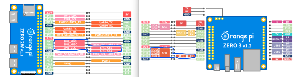
-
Hi I've made a new kernel Auxiliary Display Driver for TM16XX and compatible LED controllers. This driver supports various LED controller chips, including TM16XX family, FD6XX family, PT6964, and HBS658. It provides support for both I2C and SPI interfaces. I wanted it to manage the hardware on the kernel space while having an easy sysfs user space interface. It also aims to reduce the code to maintain by relaying on existing kernel features instead of recoding them. Plus, you can switch to hardware i2c/spi (instead of software gpio) depending on the pins used. You can use "vfdconf-convert" to convert your existing vfd.conf to its device-tree version. Or you can use the already converted vfd.conf of https://github.com/arthur-liberman/vfd-configurations that are listed in the device table. You don't need to manually edit your device tree, the "make" command will apply the device tree source overlay to your dtb. It comes with a service written as a simple bash script. So it's easily customizable without having to write custom C code. Instructions and source code at https://github.com/jefflessard/tm16xx-display/ Could you please give it a try and report your feedback?
-

Help wanted to test a new OpenVFD alternative
Jean-Francois Lessard replied to Jean-Francois Lessard's topic in Amlogic meson
Your commands looks ok, but you need to use hk1-x3, not hk1-box Your runtime device-tree do contains the display-controller under /proc/device-tree/i2c-display. So your correctly copying your dtb, but device-tree/i2c-display/sda-gpios and device-tree/i2c-display/scl-gpios shows pin of hk1-box, not hk1-x3. You also need to remove any references to OpenVFD from your device tree. This will create conflicts if you have multiple nodes using the same pins. Your dmesg also has some messages about the i2c bus on which is connected your display controller: [ 3.787786] gpio-576 (sda): enforced open drain please flag it properly in DT/ACPI DSDT/board file [ 3.792897] gpio-577 (scl): enforced open drain please flag it properly in DT/ACPI DSDT/board file [ 3.802509] i2c-gpio i2c-display: using lines 576 (SDA) and 577 (SCL) If course, you need to first configure the right pins by using hk1-x3 (and removing openvfd). Then you can investigate remaining i2c issues, if any. -
I made this simple dts file for my GPS NTP server running on Zero2/3 and Zero2w On Zero2, use PC9 as PPS in , and on Zero2W use PI5 . It should be configured in /boot/armbianEnv.txt, but I unsuccess on zero2w, so you must comment out two lines and compile it by yourself. Maybe help someone. sun50i-h616-pps-gpio.dtso
-

Armbian for an old Allwinner A10 tablet
Ryzer replied to thewiseguyshivam's topic in Allwinner sunxi
Hi, Then the only other difference would be that your device has a pin tied to usb0-vbus. The topwise dts does not have the display nodes included in the cubieboard. Now as you are currently kernel 6.1, it is possible to enable the display via overlays or compile a version of the topwise dts that includes the display nodes. So the internal display does not work under 6.1? Are there any kind of errors or does it not appear to intialise at all? Cubieboard nodes (*Note - Nodes other than hdmi and usb related have been removed): /dts-v1/; #include "sun4i-a10.dtsi" #include "sunxi-common-regulators.dtsi" #include <dt-bindings/gpio/gpio.h> / { model = "Cubietech Cubieboard"; compatible = "cubietech,a10-cubieboard", "allwinner,sun4i-a10"; hdmi-connector { compatible = "hdmi-connector"; type = "a"; port { hdmi_con_in: endpoint { remote-endpoint = <&hdmi_out_con>; }; }; }; }; &de { status = "okay"; }; &hdmi { status = "okay"; }; &hdmi_out { hdmi_out_con: endpoint { remote-endpoint = <&hdmi_con_in>; }; }; ®_usb1_vbus { status = "okay"; }; ®_usb2_vbus { status = "okay"; }; &usb_otg { dr_mode = "otg"; status = "okay"; }; &usbphy { usb0_id_det-gpios = <&pio 7 4 (GPIO_ACTIVE_HIGH | GPIO_PULL_UP)>; /* PH4 */ usb1_vbus-supply = <®_usb1_vbus>; usb2_vbus-supply = <®_usb2_vbus>; status = "okay"; }; Topwise a721: /dts-v1/; #include "sun4i-a10.dtsi" #include "sunxi-common-regulators.dtsi" #include <dt-bindings/gpio/gpio.h> #include <dt-bindings/input/input.h> #include <dt-bindings/interrupt-controller/irq.h> #include <dt-bindings/pwm/pwm.h> / { model = "Topwise A721"; compatible = "topwise,a721", "allwinner,sun4i-a10"; panel { compatible = "starry,kr070pe2t"; backlight = <&backlight>; power-supply = <®_lcd_power>; port { panel_input: endpoint { remote-endpoint = <&tcon0_out_panel>; }; }; }; reg_lcd_power: reg-lcd-power { compatible = "regulator-fixed"; regulator-name = "reg-lcd-power"; gpio = <&pio 7 8 GPIO_ACTIVE_HIGH>; /* PH8 */ enable-active-high; }; }; &de { status = "okay"; }; ®_usb0_vbus { status = "okay"; }; ®_usb1_vbus { status = "okay"; }; ®_usb2_vbus { status = "okay"; }; &tcon0_out { tcon0_out_panel: endpoint@0 { reg = <0>; remote-endpoint = <&panel_input>; }; }; &usb_otg { dr_mode = "otg"; status = "okay"; }; &usb_power_supply { status = "okay"; }; &usbphy { usb0_id_det-gpios = <&pio 7 4 GPIO_ACTIVE_HIGH>; /* PH4 */ usb0_vbus_det-gpios = <&pio 7 5 GPIO_ACTIVE_HIGH>; /* PH5 */ usb0_vbus-supply = <®_usb0_vbus>; usb1_vbus-supply = <®_usb1_vbus>; usb2_vbus-supply = <®_usb2_vbus>; status = "okay"; }; It is possible to build just uboot using the BUILD_ONLY=uboot option. Again here you could face potential issues as newer uboot might not work well with an old kernel. All the best Ryzer -
 Dear Community, I'll build a Developer Team specially for Banana Pi Boards!" GPIO Libarys I started updating/modifing the old GPIO-Libarys, so they can be used on the latest builds! I want to build a Team, for GPIO-Libary Development, for porting these Libarys: WiringPi-Node WiringPi-PHP WiringPi-Perl WirinigPi-Ruby gpiozero rpi-gpio Updating and modifying these: RPi.GPIO BPI-WiringPi2-Python BPI-WiringPi2 At the end, all currently working GPIO Libarys are: luma.oled RPi.GPIO BPI-WiringPi BPI-WiringPi2 BPI-WiringPi2-Python Armbian Build System for Banana Pi I started building the build-system for full banana pi support! Anyone who would like to join the developer-team, just pn me, post in this thread, or contact me on github or discord!" I created a GIthub-Organisation for this project and a Discord Server. A Domain & VPS Server is commin Monday!" Goals: Support ONLY for Banana Pi Boards Board Determiner Script which exports Board-Infos, required by gpio-libs (usual located at: /var/lib/bananapi) APT-Mirror Archive Hosted by our project-teams vps-server! ( Mirror stores all latest gpio-libarys we specially build for using on latest builds and other packages we'll develope in future) Added APPGROUPS: Pentesting, TV-Box, Server-Side, Game Desk & Development Revised menu for selecting extensions and other additional items Revised config menu Adding additional build options A Web-Based Project-Server Hosted Build-System will be build and available on the project-page, where you can build images remotely, according to you settings made in the WebInterface, with live progress & build-log + downloading compressed own image-release. A publish option will be added to, where you can upload your builded image to any Cloud/Storage we provide. Revised device trees According to APPGROUPS and Enabled Extensions: I2C, SPI, UART are enabled in the gpio_develope extension, and all requirements for gpio-programming are pre-installed, the gpio libs are pre-installed too. If you have some Ideas, what we could add or which wishes we can make true, just reply in this post, or contact us. Github Organisation Discord greetz, hexzhen3x7
 -
 Bumps dtschema from 2025.2 to 2025.6.1. Commits 18ac2d8 validator: Fix ordering issue with properties referencing another property 4dbacd6 tests: Add test for DTSchema.check_schema_refs() 2c5f057 schema: Rework instantiating DTSchema.validator 19c88b9 schemas: gpio-nexus-node: Fix schema $ref paths fb770c7 schema: Fix a false positive unevaluatedProperties/additionalProperties check b7f612c schemas: reset: Add '#reset-cells' into schema 7e3ef3e schemas: reset: Add descriptions from original text binding 53a2132 meta-schemas: nodes: Allow if-then-else directly in patternProperties objects 9d1305d schemas: PCI: Add standard PCIe WAKE# signal 49451a5 schemas: root-node: Add 'all-in-one' chassis-type Additional commits viewable in compare view Dependabot will resolve any conflicts with this PR as long as you don't alter it yourself. You can also trigger a rebase manually by commenting @dependabot rebase. Dependabot commands and options You can trigger Dependabot actions by commenting on this PR: @dependabot rebase will rebase this PR @dependabot recreate will recreate this PR, overwriting any edits that have been made to it @dependabot merge will merge this PR after your CI passes on it @dependabot squash and merge will squash and merge this PR after your CI passes on it @dependabot cancel merge will cancel a previously requested merge and block automerging @dependabot reopen will reopen this PR if it is closed @dependabot close will close this PR and stop Dependabot recreating it. You can achieve the same result by closing it manually @dependabot show <dependency name> ignore conditions will show all of the ignore conditions of the specified dependency @dependabot ignore this major version will close this PR and stop Dependabot creating any more for this major version (unless you reopen the PR or upgrade to it yourself) @dependabot ignore this minor version will close this PR and stop Dependabot creating any more for this minor version (unless you reopen the PR or upgrade to it yourself) @dependabot ignore this dependency will close this PR and stop Dependabot creating any more for this dependency (unless you reopen the PR or upgrade to it yourself) View the full article
 -

Driving the ili9488 LCD (4.0 inch cheap chinese clone)
robertoj replied to robertoj's topic in Allwinner sunxi
I just did some new experiments, trying to get touch working in ili9488 LCD v2.1 Increasing or decreasing the SPI MHz in both the LCD and touch section of the DTS DONT WORK... I couldn't get touch working Next is to use a software defined SPI with spi-gpio (based on my experience in my ili9341 thread) does anybody know a Python soft spi program which can talk to ads7846/xpt2046? update: I am getting some good touch results with Raspberry, which I hope I can transfer to opiz3. https://forums.raspberrypi.com/viewtopic.php?t=389230 -

Bluetooth doesn't appear after boot very often in Orange Pi 2W
IBV replied to sminder's topic in Orange Pi Zero 2
The actions in the dts for setting the GPIO pin are is based on the boot log line. marlin chip en dummy pull up -- need manually set GPIO You can check the whole discussion here and the reasoning https://chatgpt.com/share/68466d15-e5bc-8013-b200-17ae7f7c89fc However, After your last answer, Chatgpt suggests this is not really the issue, but a delayed initialisation would help. When the bt fails to initialise, try the following: sudo hciattach /dev/ttyS0 any 115200 flow sudo hciconfig hci0 up If this works, you can put this in a service to run at every boot. You can try yourself to continue the above conversation with chatgpt and see if you find the final solution. Then you can post it here. -
Bluetooth doesn't appear after boot very often in Orange Pi 2W
IBV replied to sminder's topic in Orange Pi Zero 2
Ok, if you want we can try one more thing. According to AI, the correct way to always enable the bluetooth is to do it via a custom overlay, which is not done. First, remove the bt-gpio.service, it does not help: sudo sytemctl disable bt-gpio.service sudo rm /etc/systemd/system/bt-gpio.service sudo systemctl daemon-reload Then, create the custom overlay file /boot/overlay-user/bt_enable_ph1.dts with the following content: /dts-v1/; /plugin/; &pio { bt_en_pin: bt_en_pin { pins = "PH1"; function = "gpio_out"; bias-pull-up; output-high; }; }; &uart0 { pinctrl-names = "default"; pinctrl-0 = <&uart0_pins>; status = "okay"; }; &wcn_bt { compatible = "wcn,bt"; uart = <&uart0>; enable-gpios = <&pio 7 1 GPIO_ACTIVE_HIGH>; // PH1 = GPIO 225 status = "okay"; }; Then we can try to compile and install it: sudo armbian-add-overlay /boot/overlay-user/bt_enable_ph1.dts Then activate it in /boot/armbianEnv.txt, add the following line: user_overlays=bt_enable_ph1 If all works well try to reboot and see what happens. -
Hi, I managed to make w1-GPIO work in Orange Pi Zero v3 for, for example, the DS18B20 sensor. However, I have some doubts about setting the GPIO flags for w1-gpio. Many examples provide flags in the form gpios = <&pio 0 7 (GPIO_ACTIVE_HIGH|GPIO_OPEN_DRAIN)>; but in the dts file when I use this form it does not work (syntax error) so I have to provide the flags in digital form. A description of flags and bits is here https://elixir.bootlin.com/linux/v6.6.30/source/include/dt-bindings/gpio/gpio.h If I would like to set GPIO_ACTIVE_HIGH | GPIO_OPEN_DRAIN then the digital value for these bits will be for set bits: 0110000 = 48 because GPIO_OPEN_DRAIN it is (GPIO_SINGLE_ENDED | GPIO_LINE_OPEN_DRAIN) Please help me and confirm whether I understood it correctly I wanted to get rid of the message in the logs for w1-gpio [ 4.994183] gpio-74 (onewire@0): enforced open drain please flag it properly in DT/ACPI DSDT/board file which understands that I need to set the GPIO flag GPIO_OPEN_DRAIN in the dts file I see one problem with this source https://www.kernel.org/doc/Documentation/devicetree/bindings/gpio/gpio.txt where a number of bits to set is 6 in source https://elixir.bootlin.com/linux/v6.6.30/source/include/dt-bindings/gpio/gpio.h number of bits to set is 7 I hope I posted this question in the right section, if not please move it
-
Hello everyone, I encountered an issue while using SPI with my Orange Pi 3 LTS, and now I'm going to share some solutions. Perhaps the Armbian Team can assist me in resolving the final problem. These tests were conducted on Armbian 23.02.2 Bullseye with Linux 5.15.93-sunxi64. The initial step I took to ensure the appearance of `spidev` on the Orange Pi 3 LTS was to include these configurations in `/boot/armbianEnv.txt`. overlays=spi-spidev1 param_spidev_spi_bus=0 param_spidev_spi_cs=0 Note: If `spi-spidev` and `spi-spidev1` are added together, it will not work, and the `spidev` will not appear when using the `ls /dev/sp*` command. After performing the above steps, I executed the `sudo reboot` command, and `/dev/spidev1.0` appeared. root@orangepi3-lts:~/wiringOP# ls /dev/sp* /dev/spidev1.0 However, this alone was insufficient to ensure proper functionality of SPI. I attempted to send a message to an ATMega 168p using a Python script that utilizes the `spidev` library. The script is below: import spidev spi = spidev.SpiDev() spi.open(1, 0) spi.max_speed_hz=10000 payload = [0x0c, 0x00] spi.xfer(payload) print(*payload[1:]) The ATMega 168p occasionally received the message, and sometimes it did not. I suspected that the issue might be related to the MISO or MOSI connections. To investigate further, I directly connected the MISO pin of the Orange Pi 3 LTS to its MOSI pin, testing whether I would receive an echo in the script provided earlier. Indeed, I received the echo successfully. Considering the observations so far, my remaining suspicion lies with the CS (Chip Select) line. If the CS line is not functioning properly, it may fail to select the specific device, resulting in issues with the request/response process (similar to what I experienced). Hence, I proceeded to install wiringOp, on my device. This allowed me to read all the GPIOs of my Orange Pi 3 LTS and check for any anomalies. After successfully building it, I ran the command `gpio readall` and observed the following output: root@orangepi3-lts:~/wiringOP# gpio readall +------+-----+----------+------+---+ OPi 3 +---+------+----------+-----+------+ | GPIO | wPi | Name | Mode | V | Physical | V | Mode | Name | wPi | GPIO | +------+-----+----------+------+---+----++----+---+------+----------+-----+------+ | | | 3.3V | | | 1 || 2 | | | 5V | | | | 122 | 0 | SDA.0 | OFF | 0 | 3 || 4 | | | 5V | | | | 121 | 1 | SCL.0 | OFF | 0 | 5 || 6 | | | GND | | | | 118 | 2 | PWM.0 | OFF | 0 | 7 || 8 | 0 | OFF | PL02 | 3 | 354 | | | | GND | | | 9 || 10 | 0 | OFF | PL03 | 4 | 355 | | 120 | 5 | RXD.3 | OFF | 0 | 11 || 12 | 0 | OFF | PD18 | 6 | 114 | | 119 | 7 | TXD.3 | OFF | 0 | 13 || 14 | | | GND | | | | 362 | 8 | PL10 | OFF | 0 | 15 || 16 | 0 | OFF | PD15 | 9 | 111 | | | | 3.3V | | | 17 || 18 | 0 | OFF | PD16 | 10 | 112 | | 229 | 11 | MOSI.1 | ALT2 | 0 | 19 || 20 | | | GND | | | | 230 | 12 | MISO.1 | ALT2 | 0 | 21 || 22 | 0 | OFF | PD21 | 13 | 117 | | 228 | 14 | SCLK.1 | ALT2 | 0 | 23 || 24 | 0 | OFF | CE.1 | 15 | 227 | | | | GND | | | 25 || 26 | 0 | OFF | PL08 | 16 | 360 | +------+-----+----------+------+---+----++----+---+------+----------+-----+------+ | GPIO | wPi | Name | Mode | V | Physical | V | Mode | Name | wPi | GPIO | +------+-----+----------+------+---+ OPi 3 +---+------+----------+-----+------+ I noticed that the CS pin (GPIO 227) is currently set to `OFF` and needs to be configured as `ALT2` along with `MOSI.1`, `MISO.1`, and `SCLK.1` . This information gave me a clear direction on how to solve my problem. To investigate further, I began checking the device tree configuration using the following commands: `sudo armbian-config` -> `System` -> `Dtc`: ... spi1-pins { pins = "PH4\0PH5\0PH6"; function = "spi1"; phandle = <0x2b>; }; spi1-cs-pin { pins = "PH3"; function = "spi1"; phandle = <0x2c>; }; ... spi@5011000 { compatible = "allwinner,sun50i-h6-spi\0allwinner,sun8i-h3-spi"; reg = <0x5011000 0x1000>; interrupts = <0x00 0x0b 0x04>; clocks = <0x04 0x53 0x04 0x51>; clock-names = "ahb\0mod"; dmas = <0x2a 0x17 0x2a 0x17>; dma-names = "rx\0tx"; pinctrl-names = "default"; pinctrl-0 = <0x2b 0x2c>; resets = <0x04 0x20>; status = "disabled"; #address-cells = <0x01>; #size-cells = <0x00>; phandle = <0x72>; }; ... Upon examining the pinout diagram, I realized that the Orange Pi 3 LTS utilizes SPI1, and all the SPI pins (H3, H4, H5, H6) were correctly configured in the device tree. This led me to speculate that the issue might not be in the device tree itself but rather in the `spi-spidev1 overlay`. To investigate further, I decompiled the `sun50i-h6-spi-spidev1.dtbo` file located at `/boot/dtb/allwinner/overlay/` into a `.dts` file using the command `dtc -I dtb -O dts sun50i-h6-spi-spidev1.dtbo -o sun50i-h6-sp i-spidev1.dts`. Next, I edited the `pinctrl-0` section of the `sun50i-h6-spi-spidev1.dts` file, adding the addresses `0x2b` and `0x2c` (similar to what was done in spi@5011000). /dts-v1/; / { compatible = "allwinner,sun8i-h3-spi"; fragment@0 { target-path = "/aliases"; __overlay__ { spi1 = "/soc/spi@5011000"; }; }; fragment@1 { target = <0xffffffff>; __overlay__ { pinctrl-names = "default"; pinctrl-0 = <0x2b 0x2c>; status = "okay"; #address-cells = <0x01>; #size-cells = <0x00>; spidev@0 { compatible = "armbian,spi-dev"; reg = <0x00>; spi-max-frequency = <0xf4240>; }; }; }; __fixups__ { spi1 = "/fragment@1:target:0"; spi1_pins = "/fragment@1/__overlay__:pinctrl-0:0"; }; }; Compiled the modified `sun50i-h6-spi-spidev1.dts` file into a `.dtbo` using the command `dtc -O dtb -I dts sun50i-h6-spi-spidev1.dts -o sun50i-h6-spi-spidev1.dtbo`. Then, I rebooted the Orange Pi 3 LTS. After the reboot, I ran the `gpio readall` command again to check the GPIO pin status: root@orangepi3-lts:~# gpio readall +------+-----+----------+------+---+ OPi 3 +---+------+----------+-----+------+ | GPIO | wPi | Name | Mode | V | Physical | V | Mode | Name | wPi | GPIO | +------+-----+----------+------+---+----++----+---+------+----------+-----+------+ | | | 3.3V | | | 1 || 2 | | | 5V | | | | 122 | 0 | SDA.0 | OFF | 0 | 3 || 4 | | | 5V | | | | 121 | 1 | SCL.0 | OFF | 0 | 5 || 6 | | | GND | | | | 118 | 2 | PWM.0 | OFF | 0 | 7 || 8 | 0 | OFF | PL02 | 3 | 354 | | | | GND | | | 9 || 10 | 0 | OFF | PL03 | 4 | 355 | | 120 | 5 | RXD.3 | OFF | 0 | 11 || 12 | 0 | OFF | PD18 | 6 | 114 | | 119 | 7 | TXD.3 | OFF | 0 | 13 || 14 | | | GND | | | | 362 | 8 | PL10 | OFF | 0 | 15 || 16 | 0 | OFF | PD15 | 9 | 111 | | | | 3.3V | | | 17 || 18 | 0 | OFF | PD16 | 10 | 112 | | 229 | 11 | MOSI.1 | ALT2 | 0 | 19 || 20 | | | GND | | | | 230 | 12 | MISO.1 | ALT2 | 0 | 21 || 22 | 0 | OFF | PD21 | 13 | 117 | | 228 | 14 | SCLK.1 | ALT2 | 0 | 23 || 24 | 0 | ALT2 | CE.1 | 15 | 227 | | | | GND | | | 25 || 26 | 0 | OFF | PL08 | 16 | 360 | +------+-----+----------+------+---+----++----+---+------+----------+-----+------+ | GPIO | wPi | Name | Mode | V | Physical | V | Mode | Name | wPi | GPIO | +------+-----+----------+------+---+ OPi 3 +---+------+----------+-----+------+ The SPI functionality is now operational, but this solution is not definitive. To address the underlying issue, I need assistance as device trees, kernels, and other aspects of Linux are not within my area of expertise. It seems that the problem with the CS pin is related to an error during the boot process, resulting in an incorrect address assignment. Well, I hope this information proves helpful to others who are experiencing the same issue as I did. Remember: English is not my first language, so there may be some errors.
-

Bluetooth doesn't appear after boot very often in Orange Pi 2W
sminder replied to sminder's topic in Orange Pi Zero 2
user@orangepizero2w:~$ systemctl status bt-gpio.service × bt-gpio.service - Enable GPIO for Bluetooth chip Loaded: loaded (/etc/systemd/system/bt-gpio.service; enabled; preset: enabled) Active: failed (Result: exit-code) since Tue 2025-06-10 23:18:23 +03; 11h ago Process: 489 ExecStart=/bin/sh -c echo 225 > /sys/class/gpio/export || true; echo out > /sys/class/gpio/gpio225/direction; echo 1 > /sys/class/gpio/gpio225/value (code=exited, status=2) Main PID: 489 (code=exited, status=2) CPU: 5ms jun 10 23:18:23 orangepizero2w systemd[1]: Starting bt-gpio.service - Enable GPIO for Bluetooth chip... jun 10 23:18:23 orangepizero2w sh[489]: /bin/sh: 1: echo: echo: I/O error jun 10 23:18:23 orangepizero2w sh[489]: /bin/sh: 1: cannot create /sys/class/gpio/gpio225/direction: Directory nonexistent jun 10 23:18:23 orangepizero2w sh[489]: /bin/sh: 1: cannot create /sys/class/gpio/gpio225/value: Directory nonexistent jun 10 23:18:23 orangepizero2w systemd[1]: bt-gpio.service: Main process exited, code=exited, status=2/INVALIDARGUMENT jun 10 23:18:23 orangepizero2w systemd[1]: bt-gpio.service: Failed with result 'exit-code'. jun 10 23:18:23 orangepizero2w systemd[1]: Failed to start bt-gpio.service - Enable GPIO for Bluetooth chip. Also I attached boot log which is connected to that "systemctl status bt-gpio.service" command. bt_fail_boot_log_3.txt When the board was boot correctly (BT is working fine) the output looks the same: user@orangepizero2w:~$ systemctl status bt-gpio.service × bt-gpio.service - Enable GPIO for Bluetooth chip Loaded: loaded (/etc/systemd/system/bt-gpio.service; enabled; preset: enabled) Active: failed (Result: exit-code) since Wed 2025-06-11 11:04:21 +03; 1min 30s ago Process: 492 ExecStart=/bin/sh -c echo 225 > /sys/class/gpio/export || true; echo out > /sys/class/gpio/gpio225/direction; echo 1 > /sys/class/gpio/gpio225/value (code=exited, status=2) Main PID: 492 (code=exited, status=2) CPU: 5ms jun 11 11:04:21 orangepizero2w systemd[1]: Starting bt-gpio.service - Enable GPIO for Bluetooth chip... jun 11 11:04:21 orangepizero2w sh[492]: /bin/sh: 1: echo: echo: I/O error jun 11 11:04:21 orangepizero2w sh[492]: /bin/sh: 1: cannot create /sys/class/gpio/gpio225/direction: Directory nonexistent jun 11 11:04:21 orangepizero2w sh[492]: /bin/sh: 1: cannot create /sys/class/gpio/gpio225/value: Directory nonexistent jun 11 11:04:21 orangepizero2w systemd[1]: bt-gpio.service: Main process exited, code=exited, status=2/INVALIDARGUMENT jun 11 11:04:21 orangepizero2w systemd[1]: bt-gpio.service: Failed with result 'exit-code'. jun 11 11:04:21 orangepizero2w systemd[1]: Failed to start bt-gpio.service - Enable GPIO for Bluetooth chip. -
In one post here I saw a "please buy hardware we recommend" quote, and I appreciate that, but I wasn't able to find a recommended boards list - is there even one? Or should I just use the standard/platinum support filtering on the main page? Anyway, I could also use some help / recommendation for a general purpose SBC as I ... didn't by one for years. I'm looking for a more recent SBC to run a small, low power server (think pihole, homeassistant, zigbee, etc). I don't have specific requirements, but I'd like the board to have some kind of "long term support" and I'd also like to choose something that the armbian team would recommend, maybe from a manufacturer that supports armbian directly, or at least provides good documentation. Headless install, may use GPIO, at least 3 USB ports, built-in ethernet + wifi + BT (not sure if there's an SBC that would support zigbee natively?). And also, avoid using an SD card. Ability to use eMMC or SSD would be important. Where I'm coming from: I still run two first-gen Raspberry Pis as webcams + dataloggers (the 26 pin GPIO ones with 256 and 512 MB RAM respectively) and I used OrangePi One and Lite as two surprisingly stable servers for years (one a small postfix mailserver + datalogger, the other even running 4 docker containers). I like using low-level hardware to its limits🙂 I have recently upgraded to an already outdated OrangePi PC+ that I found in the drawer - at least it has 1 GB of RAM and I was starting running into limits with the 512 MB ones. So yeah - I don't need the top of the range SBC but something ... reasonably priced (think ~40 €) that will run well for years to come. I heard good stuff about the Radxa boards with Rockchip SoCs but I have no experience as I haven't bought new SBCs in ... years. Thanks in advance 🙂
-
Bluetooth doesn't appear after boot very often in Orange Pi 2W
IBV replied to sminder's topic in Orange Pi Zero 2
I did not see the bt-gpio service starting on boot. Can you post the status ? -
Bluetooth doesn't appear after boot very often in Orange Pi 2W
IBV replied to sminder's topic in Orange Pi Zero 2
Hi, without owning this board, chatgpt is pointing out to an initialisation issue of the bluetooth system caused by the GPIO pin not being correctly handled at boot. [ 6.024062] WCN: marlin chip en dummy pull up -- need manually set GPIO The correct solution would be to handle the init in the dtb file, but you can try the following systemd initialisation as a workaround to see if it works. Create (as root) the following service file /etc/systemd/system/bt-gpio.service with the contents: [Unit] Description=Enable GPIO for Bluetooth chip Before=bluetooth.service [Service] Type=oneshot ExecStart=/bin/sh -c 'echo 225 > /sys/class/gpio/export || true; echo out > /sys/class/gpio/gpio225/direction; echo 1 > /sys/class/gpio/gpio225/value' [Install] WantedBy=multi-user.target Then enable it (as root): systemctl daemon-reexec systemctl daemon-reload systemctl enable bt-gpio.service Reboot and check if the bluetooth starts correctly. Post the boot log if it does not. -
OK, I had the fan disconnected, I have connected the fan into gpio pins and reboot system, now is 1000Mb/s, and maybe is an GND issue as eselarm commented, thank you guys
-

Efforts to develop firmware for H96 MAX V56 RK3566 8G/64G
mvpwar replied to Hqnicolas's topic in Rockchip CPU Boxes
U-Boot 2025.01-dirty (Jun 06 2025 - 16:36:43 +0000) Model: h96 TVbox 3566 DRAM: 8 GiB (effective 7.7 GiB) PMIC: RK809 (on=0x40, off=0x00) Core: 323 devices, 31 uclasses, devicetree: separate MMC: mmc@fe2b0000: 1, mmc@fe2c0000: 2, mmc@fe310000: 0 Loading Environment from nowhere... OK In: serial@fe660000 Out: serial@fe660000 Err: serial@fe660000 Model: h96 TVbox 3566 ADC channel 2 value read: 1021 setup_boot_mode: Boot mode 0x5242c300 Net: eth0: ethernet@fe010000 Hit any key to stop autoboot: 0 Scanning for bootflows in all bootdevs Seq Method State Uclass Part Name Filename --- ----------- ------ -------- ---- ------------------------ ---------------- Scanning global bootmeth 'efi_mgr': Card did not respond to voltage select! : -110 Card did not respond to voltage select! : -110 ** File not found ubootefi.var ** Failed to load EFI variables ** Unable to write file ubootefi.var ** Failed to persist EFI variables ** Unable to write file ubootefi.var ** Failed to persist EFI variables ** Unable to write file ubootefi.var ** Failed to persist EFI variables 0 efi_mgr ready (none) 0 <NULL> ** Booting bootflow '<NULL>' with efi_mgr Loading Boot0000 'mmc 0' failed EFI boot manager: Cannot load any image Boot failed (err=-14) Scanning bootdev 'mmc@fe2b0000.bootdev': Card did not respond to voltage select! : -110 Scanning bootdev 'mmc@fe310000.bootdev': 1 extlinux ready mmc 2 mmc@fe310000.bootdev.part /boot/extlinux/extlinux.conf ** Booting bootflow 'mmc@fe310000.bootdev.part_2' with extlinux U-Boot menu 1: Ubuntu 24.04.2 LTS 6.1.0-1027-rockchip 2: Ubuntu 24.04.2 LTS 6.1.0-1027-rockchip (rescue target) Enter choice: 1: Ubuntu 24.04.2 LTS 6.1.0-1027-rockchip Retrieving file: /boot/vmlinuz-6.1.0-1027-rockchip Retrieving file: /boot/initrd.img-6.1.0-1027-rockchip append: root=UUID=8bce15ff-99cf-482b-981d-3b732fcb0650 rootwait rw console=ttyS2,1500000 console=tty1 cgroup_enable=cpuset cgroup_memory=1 cgroup_enable=memory Retrieving file: /lib/firmware/6.1.0-1027-rockchip/device-tree/rockchip/rk3566-h96max-v56.dtb Skipping fdtdir /lib/firmware/6.1.0-1027-rockchip/device-tree/ for failure retrieving dts ## Flattened Device Tree blob at edecb210 Booting using the fdt blob at 0xedecb210 Working FDT set to edecb210 Loading Ramdisk to ebf24000, end ece9955c ... OK Loading Device Tree to 00000000ebf0d000, end 00000000ebf23bc7 ... OK Working FDT set to ebf0d000 Starting kernel ... [ 6.483775] Booting Linux on physical CPU 0x0000000000 [0x412fd050] [ 6.483821] Linux version 6.1.0-1027-rockchip (root@fv-az975-670) (aarch64-linux-gnu-gcc (Ubuntu 11.4.0-1ubuntu1~22.04) 11.4.0, GNU ld (GNU Binutils for Ubuntu) 2.38) #27 SMP Fri Jun 6 15:35:04 UTC 2025 [ 6.488694] Machine model: h96 TVbox 3566 [ 6.490148] efi: UEFI not found. [ 6.684612] Zone ranges: [ 6.684627] DMA [mem 0x0000000000200000-0x00000000ffffffff] [ 6.684648] DMA32 empty [ 6.684656] Normal [mem 0x0000000100000000-0x00000001ffffffff] [ 6.684667] Movable zone start for each node [ 6.684671] Early memory node ranges [ 6.684675] node 0: [mem 0x0000000000200000-0x00000000efffffff] [ 6.684689] node 0: [mem 0x0000000100000000-0x00000001ffffffff] [ 6.684700] Initmem setup node 0 [mem 0x0000000000200000-0x00000001ffffffff] [ 6.714813] On node 0, zone DMA: 512 pages in unavailable ranges [ 6.746933] cma: Reserved 16 MiB at 0x00000000ef000000 [ 6.747041] psci: probing for conduit method from DT. [ 6.747057] psci: PSCIv1.1 detected in firmware. [ 6.747067] psci: Using standard PSCI v0.2 function IDs [ 6.747075] psci: MIGRATE_INFO_TYPE not supported. [ 6.747093] psci: SMC Calling Convention v1.2 [ 6.747578] percpu: Embedded 29 pages/cpu s80504 r8192 d30088 u118784 [ 6.747786] Detected VIPT I-cache on CPU0 [ 6.747881] CPU features: detected: GIC system register CPU interface [ 6.747889] CPU features: detected: Virtualization Host Extensions [ 6.747908] CPU features: kernel page table isolation forced ON by KASLR [ 6.747917] CPU features: detected: Kernel page table isolation (KPTI) [ 6.747927] CPU features: detected: Qualcomm erratum 1009, or ARM erratum 1286807, 2441009 [ 6.747933] CPU features: detected: ARM errata 1165522, 1319367, or 1530923 [ 6.747941] alternatives: applying boot alternatives [ 6.748466] Built 1 zonelists, mobility grouping on. Total pages: 1999368 [ 6.748486] Kernel command line: root=UUID=8bce15ff-99cf-482b-981d-3b732fcb0650 rootwait rw console=ttyS2,1500000 console=tty1 cgroup_enable=cpuset cgroup_memory=1 cgroup_enable=memory [ 6.748977] Unknown kernel command line parameters "cgroup_enable=memory cgroup_memory=1", will be passed to user space. [ 6.751628] Dentry cache hash table entries: 1048576 (order: 11, 8388608 bytes, linear) [ 6.752949] Inode-cache hash table entries: 524288 (order: 10, 4194304 bytes, linear) [ 6.752965] mem auto-init: stack:off, heap alloc:off, heap free:off [ 6.752975] software IO TLB: area num 4. [ 6.795614] software IO TLB: mapped [mem 0x00000000e7f0d000-0x00000000ebf0d000] (64MB) [ 6.957563] Memory: 7826628K/8124416K available (17984K kernel code, 3690K rwdata, 12860K rodata, 7616K init, 783K bss, 281404K reserved, 16384K cma-reserved) [ 6.957848] SLUB: HWalign=64, Order=0-3, MinObjects=0, CPUs=4, Nodes=1 [ 6.957940] ftrace: allocating 73550 entries in 288 pages [ 7.175507] ftrace: allocated 288 pages with 2 groups [ 7.175725] trace event string verifier disabled [ 7.176088] rcu: Hierarchical RCU implementation. [ 7.176097] rcu: RCU event tracing is enabled. [ 7.176102] rcu: RCU restricting CPUs from NR_CPUS=8 to nr_cpu_ids=4. [ 7.176112] Rude variant of Tasks RCU enabled. [ 7.176116] Tracing variant of Tasks RCU enabled. [ 7.176121] rcu: RCU calculated value of scheduler-enlistment delay is 30 jiffies. [ 7.176128] rcu: Adjusting geometry for rcu_fanout_leaf=16, nr_cpu_ids=4 [ 7.187430] NR_IRQS: 64, nr_irqs: 64, preallocated irqs: 0 [ 7.189226] GICv3: GIC: Using split EOI/Deactivate mode [ 7.189238] GICv3: 320 SPIs implemented [ 7.189247] GICv3: 0 Extended SPIs implemented [ 7.189315] GICv3: MBI range [296:319] [ 7.189333] GICv3: Using MBI frame 0x00000000fd410000 [ 7.189389] Root IRQ handler: gic_handle_irq [ 7.189413] GICv3: GICv3 features: 16 PPIs [ 7.189460] GICv3: CPU0: found redistributor 0 region 0:0x00000000fd460000 [ 7.190098] ITS: No ITS available, not enabling LPIs [ 7.190183] rcu: srcu_init: Setting srcu_struct sizes based on contention. [ 7.193391] rockchip_clk_register_muxgrf: regmap not available [ 7.193405] rockchip_clk_register_branches: failed to register clock clk_32k_ioe: -524 [ 7.299472] arch_timer: cp15 timer(s) running at 24.00MHz (phys). [ 7.299504] clocksource: arch_sys_counter: mask: 0xffffffffffffff max_cycles: 0x588fe9dc0, max_idle_ns: 440795202592 ns [ 7.299521] sched_clock: 56 bits at 24MHz, resolution 41ns, wraps every 4398046511097ns [ 7.300681] Console: colour dummy device 80x25 [ 7.301585] printk: console [tty1] enabled [ 7.301658] Calibrating delay loop (skipped), value calculated using timer frequency.. 48.00 BogoMIPS (lpj=80000) [ 7.301703] pid_max: default: 32768 minimum: 301 [ 7.301901] LSM: Security Framework initializing [ 7.302098] AppArmor: AppArmor initialized [ 7.302368] Mount-cache hash table entries: 16384 (order: 5, 131072 bytes, linear) [ 7.302517] Mountpoint-cache hash table entries: 16384 (order: 5, 131072 bytes, linear) [ 7.306124] cblist_init_generic: Setting adjustable number of callback queues. [ 7.306172] cblist_init_generic: Setting shift to 2 and lim to 1. [ 7.306425] cblist_init_generic: Setting adjustable number of callback queues. [ 7.306462] cblist_init_generic: Setting shift to 2 and lim to 1. [ 7.306992] rcu: Hierarchical SRCU implementation. [ 7.307022] rcu: Max phase no-delay instances is 1000. [ 7.309992] EFI services will not be available. [ 7.310799] smp: Bringing up secondary CPUs ... [ 7.312169] Detected VIPT I-cache on CPU1 [ 7.312352] GICv3: CPU1: found redistributor 100 region 0:0x00000000fd480000 [ 7.312425] CPU1: Booted secondary processor 0x0000000100 [0x412fd050] [ 7.313938] Detected VIPT I-cache on CPU2 [ 7.314109] GICv3: CPU2: found redistributor 200 region 0:0x00000000fd4a0000 [ 7.314167] CPU2: Booted secondary processor 0x0000000200 [0x412fd050] [ 7.315644] Detected VIPT I-cache on CPU3 [ 7.315812] GICv3: CPU3: found redistributor 300 region 0:0x00000000fd4c0000 [ 7.315867] CPU3: Booted secondary processor 0x0000000300 [0x412fd050] [ 7.316122] smp: Brought up 1 node, 4 CPUs [ 7.316285] SMP: Total of 4 processors activated. [ 7.316309] CPU features: detected: 32-bit EL0 Support [ 7.316329] CPU features: detected: 32-bit EL1 Support [ 7.316353] CPU features: detected: Data cache clean to the PoU not required for I/D coherence [ 7.316381] CPU features: detected: Common not Private translations [ 7.316402] CPU features: detected: CRC32 instructions [ 7.316425] CPU features: detected: RCpc load-acquire (LDAPR) [ 7.316446] CPU features: detected: Privileged Access Never [ 7.316467] CPU features: detected: RAS Extension Support [ 7.316491] CPU features: detected: Speculative Store Bypassing Safe (SSBS) [ 7.316641] CPU: All CPU(s) started at EL2 [ 7.316668] alternatives: applying system-wide alternatives [ 7.320933] devtmpfs: initialized [ 7.343895] Registered cp15_barrier emulation handler [ 7.343966] Registered setend emulation handler [ 7.344315] clocksource: jiffies: mask: 0xffffffff max_cycles: 0xffffffff, max_idle_ns: 6370867519511994 ns [ 7.344383] futex hash table entries: 1024 (order: 4, 65536 bytes, linear) [ 7.345291] pinctrl core: initialized pinctrl subsystem [ 7.346546] DMI not present or invalid. [ 7.347699] NET: Registered PF_NETLINK/PF_ROUTE protocol family [ 7.349900] DMA: preallocated 1024 KiB GFP_KERNEL pool for atomic allocations [ 7.350579] DMA: preallocated 1024 KiB GFP_KERNEL|GFP_DMA pool for atomic allocations [ 7.351250] DMA: preallocated 1024 KiB GFP_KERNEL|GFP_DMA32 pool for atomic allocations [ 7.351369] audit: initializing netlink subsys (disabled) [ 7.351731] audit: type=2000 audit(0.049:1): state=initialized audit_enabled=0 res=1 [ 7.352604] Registered FIQ tty driver [ 7.353476] thermal_sys: Registered thermal governor 'fair_share' [ 7.353489] thermal_sys: Registered thermal governor 'step_wise' [ 7.353517] thermal_sys: Registered thermal governor 'user_space' [ 7.353542] thermal_sys: Registered thermal governor 'power_allocator' [ 7.353668] cpuidle: using governor menu [ 7.354303] hw-breakpoint: found 6 breakpoint and 4 watchpoint registers. [ 7.354612] ASID allocator initialised with 32768 entries [ 7.375912] platform fe0a0000.hdmi: Fixed dependency cycle(s) with /vop@fe040000/ports/port@0/endpoint@2 [ 7.398644] rockchip-gpio fdd60000.gpio: probed /pinctrl/gpio@fdd60000 [ 7.399761] rockchip-gpio fe740000.gpio: probed /pinctrl/gpio@fe740000 [ 7.400862] rockchip-gpio fe750000.gpio: probed /pinctrl/gpio@fe750000 [ 7.402019] rockchip-gpio fe760000.gpio: probed /pinctrl/gpio@fe760000 [ 7.403043] rockchip-gpio fe770000.gpio: probed /pinctrl/gpio@fe770000 [ 7.403287] rockchip-pinctrl pinctrl: probed pinctrl [ 7.405189] platform hdmi-con: Fixed dependency cycle(s) with /hdmi@fe0a0000/ports/port@1/endpoint [ 7.414022] KASLR enabled [ 7.439086] HugeTLB: registered 1.00 GiB page size, pre-allocated 0 pages [ 7.439136] HugeTLB: 0 KiB vmemmap can be freed for a 1.00 GiB page [ 7.439164] HugeTLB: registered 32.0 MiB page size, pre-allocated 0 pages [ 7.439187] HugeTLB: 0 KiB vmemmap can be freed for a 32.0 MiB page [ 7.439211] HugeTLB: registered 2.00 MiB page size, pre-allocated 0 pages [ 7.439234] HugeTLB: 0 KiB vmemmap can be freed for a 2.00 MiB page [ 7.439259] HugeTLB: registered 64.0 KiB page size, pre-allocated 0 pages [ 7.439280] HugeTLB: 0 KiB vmemmap can be freed for a 64.0 KiB page [ 7.497382] raid6: neonx8 gen() 1373 MB/s [ 7.554282] raid6: neonx4 gen() 1412 MB/s [ 7.611216] raid6: neonx2 gen() 1279 MB/s [ 7.668140] raid6: neonx1 gen() 1041 MB/s [ 7.725024] raid6: int64x8 gen() 352 MB/s [ 7.781962] raid6: int64x4 gen() 439 MB/s [ 7.838907] raid6: int64x2 gen() 354 MB/s [ 7.895823] raid6: int64x1 gen() 308 MB/s [ 7.895854] raid6: using algorithm neonx4 gen() 1412 MB/s [ 7.952635] raid6: .... xor() 1068 MB/s, rmw enabled [ 7.952666] raid6: using neon recovery algorithm [ 7.961680] iommu: Default domain type: Translated [ 7.961721] iommu: DMA domain TLB invalidation policy: strict mode [ 7.962368] SCSI subsystem initialized [ 7.962878] usbcore: registered new interface driver usbfs [ 7.962985] usbcore: registered new interface driver hub [ 7.963074] usbcore: registered new device driver usb [ 7.963370] mc: Linux media interface: v0.10 [ 7.963474] videodev: Linux video capture interface: v2.00 [ 7.963665] pps_core: LinuxPPS API ver. 1 registered [ 7.963693] pps_core: Software ver. 5.3.6 - Copyright 2005-2007 Rodolfo Giometti <giometti@linux.it> [ 7.963754] PTP clock support registered [ 7.964693] arm-scmi firmware:scmi: Enabled polling mode TX channel - prot_id:16 [ 7.964983] arm-scmi firmware:scmi: SCMI Notifications - Core Enabled. [ 7.965090] arm-scmi firmware:scmi: SCMI Protocol v2.0 'rockchip:' Firmware version 0x0 [ 7.967955] rockchip-otp fe38c000.nvmem: Failed to get clk 'usr': -2 [ 7.968000] rockchip-otp: probe of fe38c000.nvmem failed with error -2 [ 7.968240] Advanced Linux Sound Architecture Driver Initialized. [ 7.969406] Bluetooth: Core ver 2.22 [ 7.969530] NET: Registered PF_BLUETOOTH protocol family [ 7.969559] Bluetooth: HCI device and connection manager initialized [ 7.969596] Bluetooth: HCI socket layer initialized [ 7.969627] Bluetooth: L2CAP socket layer initialized [ 7.969675] Bluetooth: SCO socket layer initialized [ 7.969734] NetLabel: Initializing [ 7.969757] NetLabel: domain hash size = 128 [ 7.969777] NetLabel: protocols = UNLABELED CIPSOv4 CALIPSO [ 7.969913] NetLabel: unlabeled traffic allowed by default [ 7.972752] clocksource: Switched to clocksource arch_sys_counter [ 7.973564] VFS: Disk quotas dquot_6.6.0 [ 7.973674] VFS: Dquot-cache hash table entries: 512 (order 0, 4096 bytes) [ 7.974764] AppArmor: AppArmor Filesystem Enabled [ 7.995841] NET: Registered PF_INET protocol family [ 7.996490] IP idents hash table entries: 131072 (order: 8, 1048576 bytes, linear) [ 8.006419] tcp_listen_portaddr_hash hash table entries: 4096 (order: 5, 131072 bytes, linear) [ 8.006601] Table-perturb hash table entries: 65536 (order: 6, 262144 bytes, linear) [ 8.006770] TCP established hash table entries: 65536 (order: 7, 524288 bytes, linear) [ 8.007361] TCP bind hash table entries: 65536 (order: 10, 4194304 bytes, linear) [ 8.011210] TCP: Hash tables configured (established 65536 bind 65536) [ 8.011875] MPTCP token hash table entries: 8192 (order: 6, 393216 bytes, linear) [ 8.012342] UDP hash table entries: 4096 (order: 6, 393216 bytes, linear) [ 8.012820] UDP-Lite hash table entries: 4096 (order: 6, 393216 bytes, linear) [ 8.013530] NET: Registered PF_UNIX/PF_LOCAL protocol family [ 8.014503] RPC: Registered named UNIX socket transport module. [ 8.014540] RPC: Registered udp transport module. [ 8.014563] RPC: Registered tcp transport module. [ 8.014583] RPC: Registered tcp NFSv4.1 backchannel transport module. [ 8.014964] PCI: CLS 0 bytes, default 64 [ 8.015963] Trying to unpack rootfs image as initramfs... [ 8.017002] rockchip-thermal fe710000.tsadc: Missing tshut mode property, using default (gpio) [ 8.017052] rockchip-thermal fe710000.tsadc: Missing tshut-polarity property, using default (low) [ 8.017383] rockchip-thermal fe710000.tsadc: failed to find thermal gpio state [ 8.017422] rockchip-thermal fe710000.tsadc: failed to find thermal otpout state [ 8.019189] rockchip-thermal fe710000.tsadc: tsadc is probed successfully! [ 8.030617] hw perfevents: enabled with armv8_cortex_a55 PMU driver, 7 counters available [ 8.031845] kvm [1]: IPA Size Limit: 40 bits [ 8.031917] kvm [1]: GICv3: no GICV resource entry [ 8.031943] kvm [1]: disabling GICv2 emulation [ 8.031963] kvm [1]: GIC system register CPU interface enabled [ 8.039919] kvm [1]: vgic interrupt IRQ9 [ 8.049211] kvm [1]: VHE mode initialized successfully [ 8.711850] Initialise system trusted keyrings [ 8.712335] workingset: timestamp_bits=46 max_order=21 bucket_order=0 [ 8.727163] NFS: Registering the id_resolver key type [ 8.727283] Key type id_resolver registered [ 8.727311] Key type id_legacy registered [ 8.727493] nfs4filelayout_init: NFSv4 File Layout Driver Registering... [ 8.727531] nfs4flexfilelayout_init: NFSv4 Flexfile Layout Driver Registering... [ 8.782861] NET: Registered PF_ALG protocol family [ 8.782942] xor: measuring software checksum speed [ 8.789300] 8regs : 1565 MB/sec [ 8.794527] 32regs : 1911 MB/sec [ 8.800680] arm64_neon : 1621 MB/sec [ 8.800722] xor: using function: 32regs (1911 MB/sec) [ 8.800762] Key type asymmetric registered [ 8.800787] Asymmetric key parser 'x509' registered [ 8.800966] Block layer SCSI generic (bsg) driver version 0.4 loaded (major 242) [ 8.801442] io scheduler mq-deadline registered [ 8.801480] io scheduler kyber registered [ 8.816489] naneng-combphy fe830000.phy: Failed to get clk 'refclk': -2 [ 8.817418] naneng-combphy fe840000.phy: Failed to get clk 'refclk': -2 [ 8.822697] iep: Module initialized. [ 8.833170] dma-pl330 fe530000.dma-controller: Loaded driver for PL330 DMAC-241330 [ 8.833232] dma-pl330 fe530000.dma-controller: DBUFF-128x8bytes Num_Chans-8 Num_Peri-32 Num_Events-16 [ 8.837769] dma-pl330 fe550000.dma-controller: Loaded driver for PL330 DMAC-241330 [ 8.837832] dma-pl330 fe550000.dma-controller: DBUFF-128x8bytes Num_Chans-8 Num_Peri-32 Num_Events-16 [ 8.840875] arm-scmi firmware:scmi: Failed. SCMI protocol 22 not active. [ 8.841404] Serial: 8250/16550 driver, 10 ports, IRQ sharing disabled [ 8.842902] fe650000.serial: ttyS1 at MMIO 0xfe650000 (irq = 30, base_baud = 1500000) is a 16550A [ 8.844403] fe660000.serial: ttyS2 at MMIO 0xfe660000 (irq = 31, base_baud = 1500000) is a 16550A [ 8.971461] printk: console [ttyS2] enabled [ 8.976196] led_vk2c21_init [ 8.976196] ============================================= [ 8.976565] random: crng init done [ 8.998753] brd: module loaded [ 9.010299] loop: module loaded [ 9.011348] rbd: loaded (major 254) [ 9.012246] lkdtm: No crash points registered, enable through debugfs [ 9.019567] spi-nor spi4.0: unrecognized JEDEC id bytes: ff ff ff ff ff ff [ 9.025108] rk_gmac-dwmac fe010000.ethernet: IRQ eth_lpi not found [ 9.026201] rk_gmac-dwmac fe010000.ethernet: supply phy not found, using dummy regulator [ 9.027179] rk_gmac-dwmac fe010000.ethernet: clock input or output? (input). [ 9.027839] rk_gmac-dwmac fe010000.ethernet: TX delay(0x30). [ 9.028364] rk_gmac-dwmac fe010000.ethernet: RX delay(0x10). [ 9.028908] rk_gmac-dwmac fe010000.ethernet: integrated PHY? (no). [ 9.029657] rk_gmac-dwmac fe010000.ethernet: clock input from PHY [ 9.030572] rk_gmac-dwmac fe010000.ethernet: init for RGMII [ 9.031784] rk_gmac-dwmac fe010000.ethernet: User ID: 0x30, Synopsys ID: 0x51 [ 9.032512] rk_gmac-dwmac fe010000.ethernet: DWMAC4/5 [ 9.033088] rk_gmac-dwmac fe010000.ethernet: DMA HW capability register supported [ 9.033809] rk_gmac-dwmac fe010000.ethernet: RX Checksum Offload Engine supported [ 9.034513] rk_gmac-dwmac fe010000.ethernet: TX Checksum insertion supported [ 9.035165] rk_gmac-dwmac fe010000.ethernet: Wake-Up On Lan supported [ 9.035993] rk_gmac-dwmac fe010000.ethernet: TSO supported [ 9.036602] rk_gmac-dwmac fe010000.ethernet: Enable RX Mitigation via HW Watchdog Timer [ 9.037375] rk_gmac-dwmac fe010000.ethernet: Enabled RFS Flow TC (entries=10) [ 9.038060] rk_gmac-dwmac fe010000.ethernet: TSO feature enabled [ 9.038626] rk_gmac-dwmac fe010000.ethernet: Using 32/32 bits DMA host/device width [ 9.038888] Freeing initrd memory: 15828K [ 9.326991] usbcore: registered new interface driver asix [ 9.327593] usbcore: registered new interface driver cdc_ether [ 9.328219] usbcore: registered new interface driver rndis_host [ 9.328855] usbcore: registered new interface driver cdc_ncm [ 9.329829] VFIO - User Level meta-driver version: 0.3 [ 9.335165] naneng-combphy fe830000.phy: No refclk found [ 9.335686] naneng-combphy fe830000.phy: failed to init phy for usb3 [ 9.342658] phy phy-fe8a0000.usb2phy.1: illegal mode [ 9.343196] xhci-hcd xhci-hcd.0.auto: xHCI Host Controller [ 9.343737] xhci-hcd xhci-hcd.0.auto: new USB bus registered, assigned bus number 1 [ 9.344653] xhci-hcd xhci-hcd.0.auto: USB3 root hub has no ports [ 9.345219] xhci-hcd xhci-hcd.0.auto: hcc params 0x0220fe64 hci version 0x110 quirks 0x0000000002010010 [ 9.346198] xhci-hcd xhci-hcd.0.auto: irq 38, io mem 0xfcc00000 [ 9.347495] usb usb1: New USB device found, idVendor=1d6b, idProduct=0002, bcdDevice= 6.01 [ 9.348264] usb usb1: New USB device strings: Mfr=3, Product=2, SerialNumber=1 [ 9.348931] usb usb1: Product: xHCI Host Controller [ 9.349384] usb usb1: Manufacturer: Linux 6.1.0-1027-rockchip xhci-hcd [ 9.350016] usb usb1: SerialNumber: xhci-hcd.0.auto [ 9.351382] hub 1-0:1.0: USB hub found [ 9.351820] hub 1-0:1.0: 1 port detected [ 9.353274] xhci-hcd xhci-hcd.1.auto: xHCI Host Controller [ 9.353819] xhci-hcd xhci-hcd.1.auto: new USB bus registered, assigned bus number 2 [ 9.354726] xhci-hcd xhci-hcd.1.auto: hcc params 0x0220fe64 hci version 0x110 quirks 0x0000000002010010 [ 9.355675] xhci-hcd xhci-hcd.1.auto: irq 39, io mem 0xfd000000 [ 9.356582] xhci-hcd xhci-hcd.1.auto: xHCI Host Controller [ 9.357113] xhci-hcd xhci-hcd.1.auto: new USB bus registered, assigned bus number 3 [ 9.357833] xhci-hcd xhci-hcd.1.auto: Host supports USB 3.0 SuperSpeed [ 9.358857] usb usb2: New USB device found, idVendor=1d6b, idProduct=0002, bcdDevice= 6.01 [ 9.359669] usb usb2: New USB device strings: Mfr=3, Product=2, SerialNumber=1 [ 9.360339] usb usb2: Product: xHCI Host Controller [ 9.360794] usb usb2: Manufacturer: Linux 6.1.0-1027-rockchip xhci-hcd [ 9.361392] usb usb2: SerialNumber: xhci-hcd.1.auto [ 9.362692] hub 2-0:1.0: USB hub found [ 9.363168] hub 2-0:1.0: 1 port detected [ 9.364413] usb usb3: We don't know the algorithms for LPM for this host, disabling LPM. [ 9.365489] usb usb3: New USB device found, idVendor=1d6b, idProduct=0003, bcdDevice= 6.01 [ 9.366298] usb usb3: New USB device strings: Mfr=3, Product=2, SerialNumber=1 [ 9.366969] usb usb3: Product: xHCI Host Controller [ 9.367425] usb usb3: Manufacturer: Linux 6.1.0-1027-rockchip xhci-hcd [ 9.368024] usb usb3: SerialNumber: xhci-hcd.1.auto [ 9.369322] hub 3-0:1.0: USB hub found [ 9.369796] hub 3-0:1.0: 1 port detected [ 9.371065] usbcore: registered new interface driver cdc_acm [ 9.371596] cdc_acm: USB Abstract Control Model driver for USB modems and ISDN adapters [ 9.372854] usbcore: registered new interface driver uas [ 9.373501] usbcore: registered new interface driver usb-storage [ 9.375030] mousedev: PS/2 mouse device common for all mice [ 9.377185] i2c_dev: i2c /dev entries driver [ 9.380375] fan53555-regulator 0-001c: FAN53555 Option[12] Rev[15] Detected! [ 9.388748] rk808 0-0020: chip id: 0x8090 [ 9.389209] rk808 0-0020: No cache defaults, reading back from HW [ 9.413749] rk808 0-0020: source: on=0x40, off=0x00 [ 9.414223] rk808 0-0020: support dcdc3 fb mode:-22, 63 [ 9.415099] rk808 0-0020: support pmic reset mode:-22,0 [ 9.419325] rk808 0-0020: had get a pinctrl! [ 9.425456] rk808-regulator rk808-regulator: there is no dvs0 gpio [ 9.426146] rk808-regulator rk808-regulator: there is no dvs1 gpio [ 9.449620] rk817-battery: Failed to locate of_node [id: -1] [ 9.450385] rk817-battery rk817-battery: Failed to find matching dt id [ 9.451160] rk817-charger: Failed to locate of_node [id: -1] [ 9.451869] rk817-charger rk817-charger: Failed to find matching dt id [ 9.456870] input: rk805 pwrkey as /devices/platform/fdd40000.i2c/i2c-0/0-0020/rk805-pwrkey/input/input0 [ 9.465352] rk808-rtc rk808-rtc: registered as rtc0 [ 9.468292] rk808-rtc rk808-rtc: setting system clock to 2017-08-04T09:02:42 UTC (1501837362) [ 9.469159] rk817-codec: Failed to locate of_node [id: -1] [ 9.478300] rockchip-rga fdeb0000.rga: HW Version: 0x03.02 [ 9.479441] rockchip-rga fdeb0000.rga: Registered rockchip-rga as /dev/video0 [ 9.481339] usbcore: registered new interface driver uvcvideo [ 9.484804] cpu cpu0: bin=0 [ 9.485145] cpu cpu0: Failed to get leakage [ 9.489015] cpu cpu0: avs=0 [ 9.489616] cpu cpu0: failed to register system monitor [ 9.495187] sdhci: Secure Digital Host Controller Interface driver [ 9.495756] sdhci: Copyright(c) Pierre Ossman [ 9.496176] Synopsys Designware Multimedia Card Interface Driver [ 9.497056] sdhci-pltfm: SDHCI platform and OF driver helper [ 9.497686] dwmmc_rockchip fe2c0000.mmc: No normal pinctrl state [ 9.497695] dwmmc_rockchip fe2b0000.mmc: No normal pinctrl state [ 9.497707] dwmmc_rockchip fe2c0000.mmc: No idle pinctrl state [ 9.497716] dwmmc_rockchip fe2b0000.mmc: No idle pinctrl state [ 9.498107] dwmmc_rockchip fe2c0000.mmc: IDMAC supports 32-bit address mode. [ 9.498498] dwmmc_rockchip fe2b0000.mmc: IDMAC supports 32-bit address mode. [ 9.498906] dwmmc_rockchip fe2c0000.mmc: Using internal DMA controller. [ 9.499355] dwmmc_rockchip fe2b0000.mmc: Using internal DMA controller. [ 9.499868] dwmmc_rockchip fe2c0000.mmc: Version ID is 270a [ 9.500480] dwmmc_rockchip fe2b0000.mmc: Version ID is 270a [ 9.501188] dwmmc_rockchip fe2c0000.mmc: DW MMC controller at irq 68,32 bit host data width,256 deep fifo [ 9.501732] ledtrig-cpu: registered to indicate activity on CPUs [ 9.501759] dwmmc_rockchip fe2b0000.mmc: DW MMC controller at irq 69,32 bit host data width,256 deep fifo [ 9.502136] dwmmc_rockchip fe2b0000.mmc: Got CD GPIO [ 9.502872] arm-scmi firmware:scmi: Failed. SCMI protocol 17 not active. [ 9.504215] SMCCC: SOC_ID: ARCH_SOC_ID not implemented, skipping .... [ 9.506903] cryptodev: driver 1.12 loaded. [ 9.507799] hid: raw HID events driver (C) Jiri Kosina [ 9.508305] dwmmc_rockchip fe2c0000.mmc: allocated mmc-pwrseq [ 9.508826] usbcore: registered new interface driver usbhid [ 9.509096] mmc_host mmc2: card is non-removable. [ 9.510039] usbhid: USB HID core driver [ 9.511429] rockchip-dmc dmc: failed to get the count of devfreq-event in /dmc node [ 9.512131] rockchip-dmc dmc: failed to init opp info [ 9.512586] rockchip-dmc: probe of dmc failed with error -2 [ 9.513163] mmc_host mmc1: Bus speed (slot 0) = 375000Hz (slot req 400000Hz, actual 375000HZ div = 0) [ 9.514910] Unable to handle kernel NULL pointer dereference at virtual address 0000000000000254 [ 9.515692] Mem abort info: [ 9.515945] ESR = 0x0000000096000004 [ 9.516300] EC = 0x25: DABT (current EL), IL = 32 bits [ 9.516776] SET = 0, FnV = 0 [ 9.517051] EA = 0, S1PTW = 0 [ 9.517335] FSC = 0x04: level 0 translation fault [ 9.517769] Data abort info: [ 9.518029] ISV = 0, ISS = 0x00000004 [ 9.518371] CM = 0, WnR = 0 [ 9.518640] user pgtable: 4k pages, 48-bit VAs, pgdp=000000010546a000 [ 9.519211] [0000000000000254] pgd=0000000000000000, p4d=0000000000000000 [ 9.520476] Internal error: Oops: 0000000096000004 [#1] SMP [ 9.520980] Modules linked in: [ 9.521261] CPU: 3 PID: 1 Comm: swapper/0 Not tainted 6.1.0-1027-rockchip #27 [ 9.521897] Hardware name: h96 TVbox 3566 (DT) [ 9.522295] pstate: 60400009 (nZCv daif +PAN -UAO -TCO -DIT -SSBS BTYPE=--) [ 9.522914] pc : regmap_read+0x20/0x80 [ 9.523260] lr : px30_dfi_init+0x90/0x110 [ 9.523626] sp : ffff80000803bb00 [ 9.523925] x29: ffff80000803bb00 x28: 0000000000000000 x27: ffffb65f6a840104 [ 9.524565] x26: ffffb65f6a8b6970 x25: ffff1d360553e278 x24: ffffb65f6a9b800c [ 9.525204] x23: ffff1d36ff037830 x22: ffff1d36ff037830 x21: ffff1d360036c400 [ 9.525844] x20: ffff1d360553e380 x19: 0000000000000000 x18: 0000000000000000 [ 9.526483] x17: 0000000000000000 x16: 0000000000000000 x15: 000000000000000a [ 9.527120] x14: 0000000000000000 x13: ffffffffffffffff x12: ffffffffffffffff [ 9.527758] x11: 0000000000000001 x10: 00000000000487b1 x9 : ffffb65f6a886670 [ 9.528399] x8 : 0101010101010101 x7 : 203a732500667267 x6 : 0000000000000003 [ 9.529037] x5 : 0873131067000000 x4 : 0000000080000000 x3 : 0000000000000000 [ 9.529674] x2 : ffff80000803bb60 x1 : 0000000000000208 x0 : 0000000000000000 [ 9.530315] Call trace: [ 9.530538] regmap_read+0x20/0x80 [ 9.530853] px30_dfi_init+0x90/0x110 [ 9.531189] rockchip_dfi_probe+0xac/0x110 [ 9.531564] platform_probe+0x70/0xc0 [ 9.531898] really_probe+0x1cc/0x390 [ 9.532148] mmc0: SDHCI controller on fe310000.mmc [fe310000.mmc] using ADMA [ 9.532230] __driver_probe_device+0x13c/0x154 [ 9.533250] driver_probe_device+0x48/0xd0 [ 9.533618] __driver_attach+0x168/0x178 [ 9.533974] bus_for_each_dev+0x78/0xc4 [ 9.534320] driver_attach+0x2c/0x38 [ 9.534644] bus_add_driver+0xf8/0x20c [ 9.534982] driver_register+0xbc/0xf8 [ 9.535326] __platform_driver_register+0x30/0x3c [ 9.535750] rockchip_dfi_driver_init+0x24/0x30 [ 9.536797] do_one_initcall+0x84/0x1c4 [ 9.537145] kernel_init_freeable+0x298/0x2a0 [ 9.537544] kernel_init+0x30/0x140 [ 9.537863] ret_from_fork+0x10/0x20 [ 9.538190] [ 9.538190] PC: 0xffffb65f693a8aa4: [ 9.538633] 88a4 1a9f17e0 d5384101 f94017e3 f9429c22 eb020063 d2800002 54000080 941f5464 [ 9.539379] 88c4 52800000 17fffff8 a94153f3 a8c37bfd d50323bf d65f03c0 aa1e03e9 d503201f [ 9.540122] 88e4 f9410802 b40002c2 b941a802 34000062 6b01005f 54000243 f9404802 b5000202 [ 9.540865] 8904 d503233f a9bf7bfd 910003fd f940dc02 b40000e2 f9402c00 d63f0040 12001c00 [ 9.541608] 8924 a8c17bfd d50323bf d65f03c0 f940f402 b40000a2 97fff661 17fffff9 52800000 [ 9.542351] 8944 d65f03c0 52800020 17fffff6 aa1e03e9 d503201f d503233f a9bc7bfd 910003fd [ 9.543094] 8964 a90153f3 aa0003f3 a9025bf5 2a0103f5 aa0203f6 a90363f7 f9405c00 b5000140 [ 9.543836] 8984 f9411660 b5000100 f9406274 3949f660 340000e0 3949f260 34000240 128001f4 [ 9.544578] 89a4 14000009 aa1303f4 17fffff9 aa1603e2 2a1503e1 aa1303e0 94000a91 35fffec0 [ 9.545324] 89c4 52800014 2a1403e0 a94153f3 a9425bf5 a94363f7 a8c47bfd d50323bf d65f03c0 [ 9.546065] 89e4 2a1503e1 aa1303e0 97ffffbc 72001c1f 54000440 f9410a63 aa1403e0 aa1603e2 [ 9.546807] 8a04 2a1503e1 d63f0060 2a0003f4 35fffdc0 d000f920 91068000 91010000 b94002d8 [ 9.547550] 8a24 b9400800 7100001f 540001ad 97ffef2a b000b097 910022f7 b8606ae0 97ffef2a [ 9.548291] 8a44 72001c1f 540000c0 d2800000 2a1803e3 2a1503e2 aa1303e1 97ffef53 3949f660 [ 9.549033] 8a64 35fffb00 b94002c2 2a1503e1 aa1303e0 94000a9b 17ffffd4 12800094 17ffffd2 [ 9.550417] 8a84 aa1e03e9 d503201f d503233f a9bd7bfd 910003fd a90153f3 aa0003f3 f90013f5 [ 9.551159] 8aa4* b9425400 51000400 6a01001f 54000261 2a0103f4 aa0203f5 f9401e61 f9402660 [ 9.551901] 8ac4 d63f0020 2a1403e1 aa1503e2 aa1303e0 97ffff9f 2a0003f4 a9440261 d63f0020 [ 9.552643] 8ae4 2a1403e0 a94153f3 f94013f5 a8c37bfd d50323bf d65f03c0 128002b4 17fffff9 [ 9.553383] 8b04 aa1e03e9 d503201f d503233f a9bd7bfd 910003fd a90153f3 aa0003f3 d5384100 [ 9.554126] 8b24 aa0103f4 f9429c01 f90017e1 d2800001 b9401261 910093e2 f9400260 97ffffd1 [ 9.554868] 8b44 350000e0 b9400a62 b94027e1 0a010042 b9400e61 1ac12442 b9000282 d5384101 [ 9.555610] 8b64 f94017e3 f9429c22 eb020063 d2800002 54000040 941f53b6 a94153f3 a8c37bfd [ 9.556351] 8b84 d50323bf d65f03c0 aa1e03e9 d503201f d503233f a9bd7bfd 910003fd f9000bf3 [ 9.557093] 8ba4 2a0103f3 d5384101 f9429c22 f90017e2 d2800002 910093e1 97ffffd2 35000080 [ 9.557837] 8bc4 b94027e0 6a20027f 1a9f17e0 d5384101 f94017e3 f9429c22 eb020063 d2800002 [ 9.558579] 8be4 54000040 941f539a f9400bf3 a8c37bfd d50323bf d65f03c0 aa1e03e9 d503201f [ 9.559320] 8c04 d503233f a9bd7bfd 910003fd a90153f3 aa0003f3 d5384100 aa0203f4 f9429c02 [ 9.560062] 8c24 f90017e2 d2800002 b9401660 6b01001f 540002a9 b9401260 910093e2 b9401a63 [ 9.560803] 8c44 1b030021 f9400260 97ffff8e 350000e0 b9400a61 b94027e2 0a020021 b9400e62 [ 9.561545] 8c64 1ac22421 b9000281 d5384101 f94017e3 f9429c22 eb020063 d2800002 54000080 [ 9.562286] 8c84 941f5373 128002a0 17fffff8 a94153f3 a8c37bfd d50323bf d65f03c0 aa1e03e9 [ 9.563028] [ 9.563028] LR: 0xffffb65f6a886670: [ 9.563472] 6470 a8c57bfd d50323bf d65f03c0 aa1e03e9 d503201f d503233f a9be7bfd 910003fd [ 9.564216] 6490 f9000bf3 aa0103f3 97ffffa7 35000060 52a00021 b9008a61 f9400bf3 a8c27bfd [ 9.564957] 64b0 d50323bf d65f03c0 aa1e03e9 d503201f d503233f a9bc7bfd 910003fd a90153f3 [ 9.565699] 64d0 aa0103f3 d5384101 a9025bf5 aa0203f5 91004016 f9429c22 f9001fe2 d2800002 [ 9.567085] 64f0 52800001 f9417814 97ac067e f9002e60 b140041f 540001a8 aa1603e0 f0ffee81 [ 9.567827] 6510 911dd821 97a3902d f9003e60 aa0003e1 b140041f 54000189 f0fff662 91283c42 [ 9.568569] 6530 aa1603e0 97abe3ff d5384101 f9401fe3 f9429c22 eb020063 d2800002 54000400 [ 9.569311] 6550 97cbdd40 aa1403e0 f0ffedc1 9129c821 97cbb727 aa0003f4 b50000a0 f0fff662 [ 9.570055] 6570 12800241 9128c042 17ffffee 97ad1acf f9003260 aa1403e0 97bcffe8 f9403260 [ 9.570797] 6590 b140041f 54fffd28 52806101 9100d3e2 97ac8939 b94037e0 d34d3c01 d35c7400 [ 9.571538] 65b0 b9008261 b900b260 d0ffc9c0 913ca000 f9000ea0 52800000 17ffffdc a94153f3 [ 9.572280] 65d0 a9425bf5 a8c47bfd d50323bf d65f03c0 aa1e03e9 d503201f d503233f a9bc7bfd [ 9.573022] 65f0 910003fd a90153f3 aa0103f3 d5384101 a9025bf5 aa0203f4 aa0003f5 f9429c22 [ 9.573765] 6610 f9001fe2 d2800002 52804001 f9417816 97ac05bb aa0003e1 910042a0 979f4803 [ 9.574507] 6630 f9002e60 b140041f 54000448 90ffee81 aa1603e0 913e9021 97cbb6ed b40000a0 [ 9.575248] 6650 97ad1a9a f9003a60 b140041f 54000328 f9403a60 9100c3e2 52804101 97ac8906 [ 9.575991] 6670* 9100d3e2 f9403a60 52804181 97ac8902 f9003e7f 294603e1 531c7c02 530c7c00 [ 9.576733] 6690 d34d3c21 71000c5f 531d0400 2a000020 1a803021 52800020 b9008261 b900b260 [ 9.577476] 66b0 d0ffc9c0 913ca000 f9000e80 52800000 d5384101 f9401fe3 f9429c22 eb020063 [ 9.578219] 66d0 d2800002 54000040 97cbdcde a94153f3 a9425bf5 a8c47bfd d50323bf d65f03c0 [ 9.578961] 66f0 aa1e03e9 d503201f d503233f a9bc7bfd 910003fd a90153f3 aa0103f3 d5384101 [ 9.579703] 6710 a9025bf5 aa0203f5 aa0003f4 f9429c22 f9001fe2 d2800002 52804001 f9417816 [ 9.580445] 6730 97ac0577 aa0003e1 91004280 979f47bf f9002e60 b140041f 54000308 d0ffeda1 [ 9.581186] 6750 aa1603e0 912eb021 97cbb6a9 b40000a0 97ad1a56 f9003660 b140041f 540001e8 [ 9.581928] 6770 f9403660 9100d3e2 5280ba01 97ac88c2 b94037e0 f9003e7f d34d3c00 b9008260 [ 9.582670] 6790 52800020 b900b260 d0ffc9c0 913ca000 f9000ea0 52800000 d5384101 f9401fe3 [ 9.583411] 67b0 f9429c22 eb020063 d2800002 54000040 97cbdca4 a94153f3 a9425bf5 a8c47bfd [ 9.584153] 67d0 d50323bf d65f03c0 aa1e03e9 d503201f d503233f a9bc7bfd 910003fd a90153f3 [ 9.584894] 67f0 aa0103f3 d5384101 a9025bf5 aa0203f4 aa0003f5 f9429c22 f9001fe2 d2800002 [ 9.585636] 6810 52804001 f9417816 97ac053d aa0003e1 910042a0 979f4785 f9002e60 b140041f [ 9.586378] 6830 540004c8 d0ffeda1 aa1603e0 912eb021 97cbb66f b40000a0 97ad1a1c f9003660 [ 9.587120] 6850 b140041f 540003a8 f9403660 52804901 9100c3e2 72a000e1 97ac8887 9100d3e2 [ 9.587863] [ 9.587863] SP: 0xffff80000803bb00: [ 9.588305] b900 6a840104 ffffb65f 002d0000 ffff1d36 0803b940 ffff8000 68a32cc4 ffffb65f [ 9.589048] b920 0803b9b0 ffff8000 96000004 00000000 00000254 00000000 69bab070 ffffb65f [ 9.590433] b940 0803b970 ffff8000 69b7c288 ffffb65f 0803b9b0 ffff8000 96000004 00000000 [ 9.591176] b960 00000254 00000000 693a8aa4 ffffb65f 0803b9a0 ffff8000 69b7cfdc ffffb65f [ 9.591918] b980 00000000 00000000 0553e380 ffff1d36 0803bb00 ffff8000 ff037830 ffff1d36 [ 9.592660] b9a0 0803bae0 ffff8000 68a112e0 ffffb65f 00000000 00000000 00000208 00000000 [ 9.593401] b9c0 0803bb60 ffff8000 00000000 00000000 80000000 00000000 67000000 08731310 [ 9.594144] b9e0 00000003 00000000 00667267 203a7325 01010101 01010101 6a886670 ffffb65f [ 9.594885] ba00 000487b1 00000000 00000001 00000000 ffffffff ffffffff ffffffff ffffffff [ 9.595628] ba20 00000000 00000000 0000000a 00000000 00000000 00000000 00000000 00000000 [ 9.596369] ba40 00000000 00000000 00000000 00000000 0553e380 ffff1d36 0036c400 ffff1d36 [ 9.597110] ba60 ff037830 ffff1d36 ff037830 ffff1d36 6a9b800c ffffb65f 0553e278 ffff1d36 [ 9.597852] ba80 6a8b6970 ffffb65f 6a840104 ffffb65f 00000000 00000000 0803bb00 ffff8000 [ 9.598556] mmc0: Host Software Queue enabled [ 9.598593] baa0 6a886670 ffffb65f [ 9.598614] mmc0: new HS200 MMC card at address 0001 [ 9.598985] 0803bb00 ffff8000 693a8aa4 ffffb65f 60400009 00000000 [ 9.600312] bac0 0803bb30 ffff8000 6a88664c ffffb65f 6afdcf88 ffffb65f 6a9b800c ffffb65f [ 9.601091] bae0 0803bb00 ffff8000 693a8aa4 ffffb65f 04880a80 ffff1d36 00000000 00000000 [ 9.601790] mmcblk0: mmc0:0001 DD4064 58.2 GiB [ 9.601853] bb00* 0803bb30 ffff8000 6a886670 ffffb65f 04880a80 ffff1d36 0553e380 ffff1d36 [ 9.603016] bb20 0036c400 ffff1d36 2a33cb00 ed5202de 0803bb70 ffff8000 697da744 ffffb65f [ 9.603781] bb40 04880a80 ffff1d36 0036c400 ffff1d36 0553e380 ffff1d36 0036c410 ffff1d36 [ 9.604540] bb60 0553e380 ffff1d36 2a33cb00 ed5202de 0803bbb0 ffff8000 69388a14 ffffb65f [ 9.605317] bb80 00000000 00000000 0036c410 ffff1d36 6b26f690 ffffb65f 6b2e9ad8 ffffb65f [ 9.606092] bba0 00000000 00000000 693889fc ffffb65f 0803bbe0 ffff8000 69385b54 ffffb65f [ 9.606846] bbc0 0036c410 ffff1d36 00000000 00000000 6b26f690 ffffb65f 6b2e9ad8 ffffb65f [ 9.607592] bbe0 0803bc20 ffff8000 69385e54 ffffb65f 0036c410 ffff1d36 6b26f690 ffffb65f [ 9.608335] bc00 6b3f03a8 ffffb65f 0036c410 ffff1d36 00000000 00000000 69385dbc ffffb65f [ 9.609081] bc20 0803bc50 ffff8000 69385eb4 ffffb65f 6b3f0000 ffffb65f 6b26f690 ffffb65f [ 9.610468] bc40 6b3f03a8 ffffb65f 69386294 ffffb65f 0803bc90 ffff8000 69386554 ffffb65f [ 9.611212] bc60 0036c410 ffff1d36 6b26f690 ffffb65f 00000000 00000000 00000000 00000000 [ 9.611593] GPT:Primary header thinks Alt. header is not at the end of the disk. [ 9.611953] bc80 6b2048d0 ffffb65f 6b26f690 [ 9.611972] GPT:9400319 != 122142719 [ 9.612614] ffffb65f [ 9.612621] GPT:Alternate GPT header not at the end of the disk. [ 9.612626] 0803bcc0 [ 9.612631] GPT:9400319 != 122142719 [ 9.612639] ffff8000 [ 9.612644] GPT: Use GNU Parted to correct GPT errors. [ 9.612650] 69383410 [ 9.612678] mmcblk0: p1 p2 [ 9.613035] ffffb65f [ 9.613039] bca0 00000000 00000000 6b26f690 ffffb65f 693863ec ffffb65f 00000000 00000000 [ 9.613055] bcc0 0803bd10 ffff8000 [ 9.615526] mmcblk0boot0: mmc0:0001 DD4064 4.00 MiB [ 9.615724] 6938501c ffffb65f 6b26f690 ffffb65f 0553e200 ffff1d36 [ 9.617958] bce0 6b204bc8 ffffb65f 0553e278 ffff1d36 0803bd00 ffff8000 003448c8 ffff1d36 [ 9.618707] [ 9.618707] X2: 0xffff80000803bb60: [ 9.619155] b960 00000254 00000000 693a8aa4 ffffb65f 0803b9a0 ffff8000 69b7cfdc ffffb65f [ 9.619907] b980 00000000 00000000 0553e380 ffff1d36 0803bb00 ffff8000 ff037830 ffff1d36 [ 9.620649] b9a0 0803bae0 ffff8000 68a112e0 ffffb65f 00000000 00000000 00000208 00000000 [ 9.621396] b9c0 0803bb60 ffff8000 00000000 00000000 80000000 00000000 67000000 08731310 [ 9.622141] b9e0 00000003 00000000 00667267 203a7325 01010101 01010101 6a886670 ffffb65f [ 9.622267] mmcblk0boot1: mmc0:0001 DD4064 4.00 MiB [ 9.622884] ba00 000487b1 00000000 00000001 00000000 ffffffff ffffffff ffffffff ffffffff [ 9.622902] ba20 00000000 00000000 0000000a 00000000 00000000 00000000 00000000 00000000 [ 9.622918] ba40 00000000 00000000 00000000 00000000 0553e380 ffff1d36 0036c400 ffff1d36 [ 9.622935] ba60 ff037830 ffff1d36 ff037830 ffff1d36 6a9b800c ffffb65f 0553e278 ffff1d36 [ 9.626922] ba80 6a8b6970 ffffb65f 6a840104 ffffb65f 00000000 00000000 0803bb00 ffff8000 [ 9.627668] baa0 6a886670 ffffb65f 0803bb00 ffff8000 693a8aa4 ffffb65f 60400009 00000000 [ 9.628410] bac0 0803bb30 ffff8000 6a88664c ffffb65f 6afdcf88 ffffb65f 6a9b800c ffffb65f [ 9.629025] mmcblk0rpmb: mmc0:0001 DD4064 16.0 MiB, chardev (236:0) [ 9.629151] bae0 0803bb00 ffff8000 693a8aa4 ffffb65f 04880a80 ffff1d36 00000000 00000000 [ 9.630447] bb00 0803bb30 ffff8000 6a886670 ffffb65f 04880a80 ffff1d36 0553e380 ffff1d36 [ 9.631191] bb20 0036c400 ffff1d36 2a33cb00 ed5202de 0803bb70 ffff8000 697da744 ffffb65f [ 9.631933] bb40 04880a80 ffff1d36 0036c400 ffff1d36 0553e380 ffff1d36 0036c410 ffff1d36 [ 9.632676] bb60* 0553e380 ffff1d36 2a33cb00 ed5202de 0803bbb0 ffff8000 69388a14 ffffb65f [ 9.633419] bb80 00000000 00000000 0036c410 ffff1d36 6b26f690 ffffb65f 6b2e9ad8 ffffb65f [ 9.634162] bba0 00000000 00000000 693889fc ffffb65f 0803bbe0 ffff8000 69385b54 ffffb65f [ 9.634905] bbc0 0036c410 ffff1d36 00000000 00000000 6b26f690 ffffb65f 6b2e9ad8 ffffb65f [ 9.635647] bbe0 0803bc20 ffff8000 69385e54 ffffb65f 0036c410 ffff1d36 6b26f690 ffffb65f [ 9.636389] bc00 6b3f03a8 ffffb65f 0036c410 ffff1d36 00000000 00000000 69385dbc ffffb65f [ 9.637130] bc20 0803bc50 ffff8000 69385eb4 ffffb65f 6b3f0000 ffffb65f 6b26f690 ffffb65f [ 9.637873] bc40 6b3f03a8 ffffb65f 69386294 ffffb65f 0803bc90 ffff8000 69386554 ffffb65f [ 9.638614] bc60 0036c410 ffff1d36 6b26f690 ffffb65f 00000000 00000000 00000000 00000000 [ 9.639357] bc80 6b2048d0 ffffb65f 6b26f690 ffffb65f 0803bcc0 ffff8000 69383410 ffffb65f [ 9.640099] bca0 00000000 00000000 6b26f690 ffffb65f 693863ec ffffb65f 00000000 00000000 [ 9.640843] bcc0 0803bd10 ffff8000 6938501c ffffb65f 6b26f690 ffffb65f 0553e200 ffff1d36 [ 9.641584] bce0 6b204bc8 ffffb65f 0553e278 ffff1d36 0803bd00 ffff8000 003448c8 ffff1d36 [ 9.642326] bd00 00b71378 ffff1d36 2a33cb00 ed5202de 0803bd20 ffff8000 693848cc ffffb65f [ 9.643068] bd20 0803bd70 ffff8000 69387100 ffffb65f 6b26f690 ffffb65f 6b2bca60 ffffb65f [ 9.643810] bd40 6b351000 ffffb65f 00000000 00000000 008ff400 ffff1d36 6a9b800c ffffb65f [ 9.644555] [ 9.644555] X9: 0xffffb65f6a886670: [ 9.644998] 6470 a8c57bfd d50323bf d65f03c0 aa1e03e9 d503201f d503233f a9be7bfd 910003fd [ 9.645740] 6490 f9000bf3 aa0103f3 97ffffa7 35000060 52a00021 b9008a61 f9400bf3 a8c27bfd [ 9.647125] 64b0 d50323bf d65f03c0 aa1e03e9 d503201f d503233f a9bc7bfd 910003fd a90153f3 [ 9.647867] 64d0 aa0103f3 d5384101 a9025bf5 aa0203f5 91004016 f9429c22 f9001fe2 d2800002 [ 9.648609] 64f0 52800001 f9417814 97ac067e f9002e60 b140041f 540001a8 aa1603e0 f0ffee81 [ 9.649351] 6510 911dd821 97a3902d f9003e60 aa0003e1 b140041f 54000189 f0fff662 91283c42 [ 9.650093] 6530 aa1603e0 97abe3ff d5384101 f9401fe3 f9429c22 eb020063 d2800002 54000400 [ 9.650834] 6550 97cbdd40 aa1403e0 f0ffedc1 9129c821 97cbb727 aa0003f4 b50000a0 f0fff662 [ 9.651577] 6570 12800241 9128c042 17ffffee 97ad1acf f9003260 aa1403e0 97bcffe8 f9403260 [ 9.652319] 6590 b140041f 54fffd28 52806101 9100d3e2 97ac8939 b94037e0 d34d3c01 d35c7400 [ 9.653062] 65b0 b9008261 b900b260 d0ffc9c0 913ca000 f9000ea0 52800000 17ffffdc a94153f3 [ 9.653804] 65d0 a9425bf5 a8c47bfd d50323bf d65f03c0 aa1e03e9 d503201f d503233f a9bc7bfd [ 9.654546] 65f0 910003fd a90153f3 aa0103f3 d5384101 a9025bf5 aa0203f4 aa0003f5 f9429c22 [ 9.655288] 6610 f9001fe2 d2800002 52804001 f9417816 97ac05bb aa0003e1 910042a0 979f4803 [ 9.656029] 6630 f9002e60 b140041f 54000448 90ffee81 aa1603e0 913e9021 97cbb6ed b40000a0 [ 9.656772] 6650 97ad1a9a f9003a60 b140041f 54000328 f9403a60 9100c3e2 52804101 97ac8906 [ 9.657513] 6670* 9100d3e2 f9403a60 52804181 97ac8902 f9003e7f 294603e1 531c7c02 530c7c00 [ 9.658255] 6690 d34d3c21 71000c5f 531d0400 2a000020 1a803021 52800020 b9008261 b900b260 [ 9.658997] 66b0 d0ffc9c0 913ca000 f9000e80 52800000 d5384101 f9401fe3 f9429c22 eb020063 [ 9.659739] 66d0 d2800002 54000040 97cbdcde a94153f3 a9425bf5 a8c47bfd d50323bf d65f03c0 [ 9.660480] 66f0 aa1e03e9 d503201f d503233f a9bc7bfd 910003fd a90153f3 aa0103f3 d5384101 [ 9.661223] 6710 a9025bf5 aa0203f5 aa0003f4 f9429c22 f9001fe2 d2800002 52804001 f9417816 [ 9.661965] 6730 97ac0577 aa0003e1 91004280 979f47bf f9002e60 b140041f 54000308 d0ffeda1 [ 9.662707] 6750 aa1603e0 912eb021 97cbb6a9 b40000a0 97ad1a56 f9003660 b140041f 540001e8 [ 9.663449] 6770 f9403660 9100d3e2 5280ba01 97ac88c2 b94037e0 f9003e7f d34d3c00 b9008260 [ 9.664193] 6790 52800020 b900b260 d0ffc9c0 913ca000 f9000ea0 52800000 d5384101 f9401fe3 [ 9.664935] 67b0 f9429c22 eb020063 d2800002 54000040 97cbdca4 a94153f3 a9425bf5 a8c47bfd [ 9.665678] 67d0 d50323bf d65f03c0 aa1e03e9 d503201f d503233f a9bc7bfd 910003fd a90153f3 [ 9.667061] 67f0 aa0103f3 d5384101 a9025bf5 aa0203f4 aa0003f5 f9429c22 f9001fe2 d2800002 [ 9.667802] 6810 52804001 f9417816 97ac053d aa0003e1 910042a0 979f4785 f9002e60 b140041f [ 9.668544] 6830 540004c8 d0ffeda1 aa1603e0 912eb021 97cbb66f b40000a0 97ad1a1c f9003660 [ 9.669286] 6850 b140041f 540003a8 f9403660 52804901 9100c3e2 72a000e1 97ac8887 9100d3e2 [ 9.670033] [ 9.670033] X20: 0xffff1d360553e380: [ 9.670485] e180 0553e280 ffff1d36 0553e080 ffff1d36 00000001 00000000 00000000 00000000 [ 9.671228] e1a0 6b26f428 ffffb65f 00000000 00000000 00000000 00000000 00000000 00000000 [ 9.671969] e1c0 00000000 00000000 00000000 00000000 00000000 00000000 00000000 00000000 [ 9.672712] e1e0 00000000 00000000 00000000 00000000 00000000 00000000 00000000 00000000 [ 9.673453] e200 6a755a6c ffffb65f 00afec00 ffff1d36 0553e108 ffff1d36 00afec28 ffff1d36 [ 9.674196] e220 00afec00 ffff1d36 6b204960 ffffb65f 05539980 ffff1d36 00000001 00000003 [ 9.674937] e240 00000000 dead4ead ffffffff 00000000 ffffffff ffffffff 0553e258 ffff1d36 [ 9.675679] e260 0553e258 ffff1d36 00000000 00000000 00000000 00000000 00344900 ffff1d36 [ 9.676421] e280 00344918 ffff1d36 0553e180 ffff1d36 00000001 00000000 00000000 00000000 [ 9.677164] e2a0 6b26f690 ffffb65f 00000000 00000000 00000000 00000000 00000000 00000000 [ 9.677904] e2c0 00000000 00000000 00000000 00000000 00000000 00000000 00000000 00000000 [ 9.678647] e2e0 00000000 00000000 00000000 00000000 00000000 00000000 00000000 00000000 [ 9.679389] e300 0553e400 ffff1d36 04880a00 ffff1d36 6938b0d0 ffffb65f 6a6b4aa6 ffffb65f [ 9.680130] e320 00000020 00000000 00000000 00000000 00000000 00000000 00000000 00000000 [ 9.680871] e340 00000000 00000000 00000000 00000000 00000000 00000000 00000000 00000000 [ 9.681612] e360 00000000 00000000 00000000 00000000 00000000 00000000 00000000 00000000 [ 9.682353] e380* 00000000 00000000 00000000 00000000 00000000 00000000 00000000 00000000 [ 9.683095] e3a0 00000000 00000000 00000000 00000000 00000000 00000000 00000000 00000000 [ 9.683836] e3c0 00000000 00000000 00000000 00000000 00000000 00000000 00000000 00000000 [ 9.684577] e3e0 00000000 00000000 00000000 00000000 00000000 00000000 00000000 00000000 [ 9.685319] e400 0553e500 ffff1d36 0553e300 ffff1d36 6938b0d0 ffffb65f 6a6b4aa6 ffffb65f [ 9.686060] e420 0000001a 00000000 00000000 00000000 00000000 00000000 00000000 00000000 [ 9.687453] e440 00000000 00000000 00000000 00000000 00000000 00000000 00000000 00000000 [ 9.688194] e460 00000000 00000000 00000000 00000000 00000000 00000000 00000000 00000000 [ 9.688935] e480 33326566 30303030 6966642e 69666420 32656640 30303033 00000030 00000000 [ 9.689678] e4a0 00000000 00000000 00000000 00000000 00000000 00000000 00000000 00000000 [ 9.690420] e4c0 00000000 00000000 00000000 00000000 00000000 00000000 00000000 00000000 [ 9.691162] e4e0 00000000 00000000 00000000 00000000 00000000 00000000 00000000 00000000 [ 9.691905] e500 0553e600 ffff1d36 0553e400 ffff1d36 68a8dbe8 ffffb65f 6a5deb68 ffffb65f [ 9.692647] e520 00000018 00000000 00000000 00000000 00000000 00000000 00000000 00000000 [ 9.693388] e540 00000000 00000000 00000000 00000000 00000000 00000000 00000000 00000000 [ 9.694129] e560 00000000 00000000 00000000 00000000 00000000 00000000 00000000 00000000 [ 9.694871] [ 9.694871] X21: 0xffff1d360036c400: [ 9.695322] c200 0036c1f8 ffff1d36 00000000 00000000 00000000 00000000 00000081 00000000 [ 9.696065] c220 00000000 00000002 ffffffff 00000000 00000000 00000000 00000000 00000000 [ 9.696807] c240 00000000 00000000 00000000 00000000 00000000 00000000 00000000 00000000 [ 9.697549] c260 00000000 00000000 00000000 00000000 00000000 00000000 00000000 00000000 [ 9.698290] c280 00000000 00000000 00000000 00000000 00000000 00000000 00000000 00000000 [ 9.699034] c2a0 0036c368 ffff1d36 ffffffff 00000000 00000000 00000000 00000000 00000000 [ 9.699777] c2c0 0036c370 ffff1d36 0036c2c8 ffff1d36 0036c2c8 ffff1d36 00000000 00000000 [ 9.700519] c2e0 00000000 00000000 6b399408 ffffb65f ff0375a8 ffff1d36 ff0375c0 ffff1d36 [ 9.701264] c300 00000000 00000000 00000000 dead4ead ffffffff 00000000 ffffffff ffffffff [ 9.702005] c320 0036c320 ffff1d36 0036c320 ffff1d36 00000000 00000000 00000000 00000000 [ 9.702747] c340 693884cc ffffb65f 00000000 00000000 00000000 00000000 00000000 00000000 [ 9.703489] c360 00000000 00000000 ffffffff 00000000 00000000 00000000 00000000 00000000 [ 9.704230] c380 00000001 00000000 00b6e900 ffff1d36 00000000 00000000 00000000 00000000 [ 9.704972] c3a0 00000000 00000000 00000000 00000000 00000000 00000000 00000000 00000000 [ 9.705715] c3c0 00000000 00000000 00000000 00000000 00000000 00000000 00000000 00000000 [ 9.707097] c3e0 00000000 00000000 00000000 00000000 00000000 00000000 00000000 00000000 [ 9.707842] c400* 00b6eb80 ffff1d36 ffffffff 00000000 00b6eb80 ffff1d36 0036d418 ffff1d36 [ 9.708585] c420 0036c018 ffff1d36 6b204ca8 ffffb65f 008fa980 ffff1d36 6b2044b0 ffffb65f [ 9.709326] c440 00b72b80 ffff1d36 00000003 00000007 6b204ca8 ffffb65f 00b71300 ffff1d36 [ 9.710068] c460 00000000 00000000 00000000 00000000 6b204bc8 ffffb65f 6b26f690 ffffb65f [ 9.710809] c480 00000000 00000000 00000000 00000000 002d0000 ffff1d36 00000000 dead4ead [ 9.711550] c4a0 ffffffff 00000000 ffffffff ffffffff 00000000 00000000 0036c4b8 ffff1d36 [ 9.712292] c4c0 0036c4b8 ffff1d36 0036c4c8 ffff1d36 0036c4c8 ffff1d36 0036c4d8 ffff1d36 [ 9.713034] c4e0 0036c4d8 ffff1d36 0036c4e8 ffff1d36 0036c4e8 ffff1d36 00000001 00000000 [ 9.713776] c500 00000000 00000104 00000000 00000000 00000000 dead4ead ffffffff 00000000 [ 9.714518] c520 ffffffff ffffffff 0036d528 ffff1d36 0036c128 ffff1d36 ffffffff 00000000 [ 9.715259] c540 00000000 dead4ead ffffffff 00000000 ffffffff ffffffff 0036c558 ffff1d36 [ 9.716001] c560 0036c558 ffff1d36 00000000 00000000 00000000 00000000 0036c578 ffff1d36 [ 9.716743] c580 00000000 00000000 00000000 00000000 00000000 00000000 00000000 00000000 [ 9.717484] c5a0 69395fb8 ffffb65f fef8b480 ffff1d36 00000000 00000000 00000000 00000000 [ 9.718226] c5c0 ffffffe0 0000000f 0036c5c8 ffff1d36 0036c5c8 ffff1d36 693965f0 ffffb65f [ 9.718968] c5e0 00000000 dead4ead ffffffff 00000000 ffffffff ffffffff 0036c5f8 ffff1d36 [ 9.719712] [ 9.719712] X22: 0xffff1d36ff037830: [ 9.720162] 7630 ff0378b8 ffff1d36 ff0373a8 ffff1d36 ff010e58 ffff1d36 008fa080 ffff1d36 [ 9.720905] 7650 6b26e708 ffffb65f 00a2d080 ffff1d36 00000003 00000003 00000008 00000000 [ 9.721648] 7670 00000000 00000000 40736f71 61316566 30303138 00000000 fdd1e7f0 fffffbff [ 9.722391] 7690 0000001b 00000000 fdd12fcc fffffbff ff0376f0 ffff1d36 00000000 00000000 [ 9.723133] 76b0 00a2e080 ffff1d36 00000124 00000000 0000001b 00000000 00000000 00000000 [ 9.723875] 76d0 00000000 00000000 697c6038 ffffb65f 00000000 00000000 00000000 00000000 [ 9.724617] 76f0 fdd1e8cb fffffbff 00000010 00000000 fdd12ff4 fffffbff ff037758 ffff1d36 [ 9.725359] 7710 00000000 00000000 00a2e180 ffff1d36 00000124 00000000 00000010 00000000 [ 9.726744] 7730 00000000 00000000 00000000 00000000 697c6038 ffffb65f 00000000 00000000 [ 9.726781] mmc_host mmc2: Bus speed (slot 0) = 375000Hz (slot req 400000Hz, actual 375000HZ div = 0) [ 9.727485] 7750 00000000 00000000 fdd1e97b fffffbff 00000004 00000000 fdd13010 fffffbff [ 9.729035] 7770 ff0377c0 ffff1d36 00000000 00000000 00a2e280 ffff1d36 00000124 00000000 [ 9.729777] 7790 00000004 00000000 00000000 00000000 00000000 00000000 697c6038 ffffb65f [ 9.730519] 77b0 00000000 00000000 00000000 00000000 6a60e7f3 ffffb65f 00000004 00000000 [ 9.731260] 77d0 ff037828 ffff1d36 00000000 00000000 00000000 00000000 00a2e380 ffff1d36 [ 9.732006] 77f0 00000124 00000000 00000004 00000000 00000000 00000000 00000000 00000000 [ 9.732748] 7810 697c6038 ffffb65f 00000000 00000000 00000000 00000000 00736f71 00000000 [ 9.733490] 7830* ff037b80 ffff1d36 000000fb 00000000 ff037900 ffff1d36 00000000 00000000 [ 9.734232] 7850 6a1bda80 ffffb65f 0036c410 ffff1d36 ff037860 ffff1d36 ff037860 ffff1d36 [ 9.734974] 7870 ff037870 ffff1d36 ff037870 ffff1d36 00000001 00000000 ff037910 ffff1d36 [ 9.735716] 7890 00000000 00000000 ff010dd8 ffff1d36 00000000 00000000 ff037b88 ffff1d36 [ 9.736457] 78b0 00a2e500 ffff1d36 ff037c10 ffff1d36 ff037630 ffff1d36 ff010e58 ffff1d36 [ 9.737199] 78d0 008fa080 ffff1d36 6b26e708 ffffb65f 00a2d300 ffff1d36 00000003 00000003 [ 9.737942] 78f0 00000008 00000000 00000000 00000000 40696664 33326566 30303030 00000000 [ 9.738684] 7910 fdd1e7f0 fffffbff 00000014 00000000 fdd13038 fffffbff ff037978 ffff1d36 [ 9.739426] 7930 00000000 00000000 00a2e480 ffff1d36 00000124 00000000 00000014 00000000 [ 9.740168] 7950 00000000 00000000 00000000 00000000 697c6038 ffffb65f 00000000 00000000 [ 9.740909] 7970 00000000 00000000 fdd1e8cb fffffbff 00000010 00000000 fdd13058 fffffbff [ 9.741652] 7990 ff0379e0 ffff1d36 00000000 00000000 00a2e680 ffff1d36 00000124 00000000 [ 9.742393] 79b0 00000010 00000000 00000000 00000000 00000000 00000000 697c6038 ffffb65f [ 9.743774] 79d0 00000000 00000000 00000000 00000000 fdd1ea59 fffffbff 0000000c 00000000 [ 9.744516] 79f0 fdd13074 fffffbff ff037a48 ffff1d36 00000000 00000000 00a2e780 ffff1d36 [ 9.745259] 7a10 00000124 00000000 0000000c 00000000 00000000 00000000 00000000 00000000 [ 9.746002] [ 9.746002] X23: 0xffff1d36ff037830: [ 9.746452] 7630 ff0378b8 ffff1d36 ff0373a8 ffff1d36 ff010e58 ffff1d36 008fa080 ffff1d36 [ 9.747194] 7650 6b26e708 ffffb65f 00a2d080 ffff1d36 00000003 00000003 00000008 00000000 [ 9.747936] 7670 00000000 00000000 40736f71 61316566 30303138 00000000 fdd1e7f0 fffffbff [ 9.748677] 7690 0000001b 00000000 fdd12fcc fffffbff ff0376f0 ffff1d36 00000000 00000000 [ 9.749419] 76b0 00a2e080 ffff1d36 00000124 00000000 0000001b 00000000 00000000 00000000 [ 9.750161] 76d0 00000000 00000000 697c6038 ffffb65f 00000000 00000000 00000000 00000000 [ 9.750903] 76f0 fdd1e8cb fffffbff 00000010 00000000 fdd12ff4 fffffbff ff037758 ffff1d36 [ 9.751644] 7710 00000000 00000000 00a2e180 ffff1d36 00000124 00000000 00000010 00000000 [ 9.752386] 7730 00000000 00000000 00000000 00000000 697c6038 ffffb65f 00000000 00000000 [ 9.753127] 7750 00000000 00000000 fdd1e97b fffffbff 00000004 00000000 fdd13010 fffffbff [ 9.753868] 7770 ff0377c0 ffff1d36 00000000 00000000 00a2e280 ffff1d36 00000124 00000000 [ 9.754610] 7790 00000004 00000000 00000000 00000000 00000000 00000000 697c6038 ffffb65f [ 9.755351] 77b0 00000000 00000000 00000000 00000000 6a60e7f3 ffffb65f 00000004 00000000 [ 9.756738] 77d0 ff037828 ffff1d36 00000000 00000000 00000000 00000000 00a2e380 ffff1d36 [ 9.757479] 77f0 00000124 00000000 00000004 00000000 00000000 00000000 00000000 00000000 [ 9.758219] 7810 697c6038 ffffb65f 00000000 00000000 00000000 00000000 00736f71 00000000 [ 9.758961] 7830* ff037b80 ffff1d36 000000fb 00000000 ff037900 ffff1d36 00000000 00000000 [ 9.759703] 7850 6a1bda80 ffffb65f 0036c410 ffff1d36 ff037860 ffff1d36 ff037860 ffff1d36 [ 9.760446] 7870 ff037870 ffff1d36 ff037870 ffff1d36 00000001 00000000 ff037910 ffff1d36 [ 9.761188] 7890 00000000 00000000 ff010dd8 ffff1d36 00000000 00000000 ff037b88 ffff1d36 [ 9.761930] 78b0 00a2e500 ffff1d36 ff037c10 ffff1d36 ff037630 ffff1d36 ff010e58 ffff1d36 [ 9.762672] 78d0 008fa080 ffff1d36 6b26e708 ffffb65f 00a2d300 ffff1d36 00000003 00000003 [ 9.763413] 78f0 00000008 00000000 00000000 00000000 40696664 33326566 30303030 00000000 [ 9.764155] 7910 fdd1e7f0 fffffbff 00000014 00000000 fdd13038 fffffbff ff037978 ffff1d36 [ 9.764898] 7930 00000000 00000000 00a2e480 ffff1d36 00000124 00000000 00000014 00000000 [ 9.765640] 7950 00000000 00000000 00000000 00000000 697c6038 ffffb65f 00000000 00000000 [ 9.766381] 7970 00000000 00000000 fdd1e8cb fffffbff 00000010 00000000 fdd13058 fffffbff [ 9.767123] 7990 ff0379e0 ffff1d36 00000000 00000000 00a2e680 ffff1d36 00000124 00000000 [ 9.767865] 79b0 00000010 00000000 00000000 00000000 00000000 00000000 697c6038 ffffb65f [ 9.768610] 79d0 00000000 00000000 00000000 00000000 fdd1ea59 fffffbff 0000000c 00000000 [ 9.769351] 79f0 fdd13074 fffffbff ff037a48 ffff1d36 00000000 00000000 00a2e780 ffff1d36 [ 9.770093] 7a10 00000124 00000000 0000000c 00000000 00000000 00000000 00000000 00000000 [ 9.770835] [ 9.770835] X24: 0xffffb65f6a9b800c: [ 9.771284] 7e0c ffec1214 ffec1248 ffec127c ffec12c4 ffec1418 ffec15a8 ffec15f8 ffec1620 [ 9.772026] 7e2c ffec1ba0 ffec1c18 ffec1f00 ffec1f2c ffec1f60 ffec1f8c ffec1fb8 ffec1fe4 [ 9.773406] 7e4c ffec2104 ffec2180 ffec21d0 ffec2274 ffec22c4 ffec2340 ffec23b8 ffec23f8 [ 9.774147] 7e6c ffec2508 ffec2574 ffec25c4 ffec26c0 ffec26e8 ffec2848 ffec2870 ffec2898 [ 9.774891] 7e8c ffec28c0 ffec28e8 ffec2910 ffec2938 ffec2960 ffec298c ffec29b8 ffec2a0c [ 9.775632] 7eac ffec2a38 ffec2a60 ffec2a8c ffec2ab4 ffec2adc ffec2b04 ffec2c44 ffec2c70 [ 9.776375] 7ecc ffec2c9c ffec2cc8 ffec2e6c ffec2f28 ffec2f50 ffec2f9c ffec2fc8 fec2f278 [ 9.777117] 7eec ffec2ff0 ffec3024 ffec3050 ffec3138 ffec3164 ffec3288 ffec3368 ffec33c4 [ 9.777859] 7f0c ffec35d0 ffec365c ffec3688 ffec36b4 fece25d4 ffec3a80 ffec3b18 ffec3c84 [ 9.778600] 7f2c ffec3cb0 ffec3ce0 ffec3edc ffec3f08 ffec3f34 ffec3fcc ffec3ff8 ffec4024 [ 9.779343] 7f4c ffec4050 ffec407c ffec40a8 ffec4494 ffec4688 ffec46b8 ffec493c ffec4a80 [ 9.780085] 7f6c ffec4aac ffec4ad8 ffec4bec ffec4c18 ffec4c50 ffec4c7c ffec4ca8 ffec4cd4 [ 9.780827] 7f8c ffec4d00 ffec4d2c ffec4dc4 ffec4df0 ffec4e1c ffec4e44 ffec4e6c ffec4edc [ 9.781569] 7fac ffec4f2c ffec4f84 ffec4fac ffec4fd4 ffec50f8 ffec5150 ffec5178 ffec51a0 [ 9.782311] 7fcc ffec51f0 ffec5248 ffec6988 ffec8698 ffec8b80 ffec9920 ffec9cf4 ffec9e54 [ 9.783052] 7fec ffec9e80 ffecb4c8 ffecb660 ffecb688 ffecb6bc ffece2a4 ffece2d0 ffece2fc [ 9.783793] 800c* ffece8ec ffece918 ffece94c ffecea2c ffecea58 ffecea84 ffeceab0 ffeceadc [ 9.784535] 802c ffeceb08 ffeceb34 ffecec50 ffecedec fee4e750 ffecf1e8 ffecf26c ffecf474 [ 9.785277] 804c ffecf5a8 ffecf6c4 ffecf704 ffecfc8c ffecfd6c ffecfd98 ffecfdcc ffecff40 [ 9.786019] 806c ffecffc0 ffed0014 ffed0040 ffed006c ffed0098 ffed00c4 ffed00f0 ffed011c [ 9.787399] 808c ffed0148 ffed0174 ffed01a0 ffed01cc ffed01f8 ffed0224 ffed0250 ffed027c [ 9.788141] 80ac ffed02a8 ffed02d4 ffed0300 ffed032c ffed03b0 ffed03dc ffed0408 ffed0434 [ 9.788882] 80cc ffed0460 ffed048c ffed04b8 ffed04e4 ffed0510 ffed053c ffed0f80 ffed1488 [ 9.789624] 80ec ffed19f0 ffed1b44 ffed3374 ffed34fc ffed3550 ffed5948 ffed5e1c ffed6178 [ 9.790366] 810c ffed6844 ffed68cc ffed6ef0 ffed6f3c ffed7024 ffed7138 ffeb9900 ffeb9950 [ 9.791108] 812c ffec3170 ffec31cc ffec31f8 ffec3224 ffec3250 ffec327c ffec32a8 ffec32d4 [ 9.791849] 814c ffec3300 ffec332c ffec3358 ffec33b4 ffec33e0 ffec349c ffe8a954 ffe931dc [ 9.792591] 816c ffe93218 ffe937ac ffe937e8 ffe94ad0 ffe94efc ffe95738 ffe958ac ffe958ec [ 9.793333] 818c ffe9612c ffe95af0 ffe963fc ffe9647c ffe969f4 ffe977f8 ffe98a14 ffe99ffc [ 9.794075] 81ac ffe9a3bc ffe9a440 ffe9acf8 ffe9b78c ffe9bca0 ffe9bcdc ffe9bfd0 ffe9dd3c [ 9.794817] 81cc ffe9e034 ffe9e184 ffe9e238 ffe9e264 ffe9e2d0 ffe9e400 ffe9e444 ffe9e488 [ 9.795559] 81ec ffe9e5fc ffe9ed04 ffea0cf4 ffea395c ffea5fbc ffea6cd8 ffea6e78 ffea8bc8 [ 9.796301] [ 9.796301] X25: 0xffff1d360553e278: [ 9.796752] e078 00344900 ffff1d36 0553e180 ffff1d36 0568b480 ffff1d36 00000001 00000000 [ 9.797495] e098 00000000 00000000 6b26f298 ffffb65f 00000000 00000000 00000000 00000000 [ 9.798237] e0b8 00000000 00000000 00000000 00000000 00000000 00000000 00000000 00000000 [ 9.798979] e0d8 00000000 00000000 00000000 00000000 00000000 00000000 00000000 00000000 [ 9.799720] e0f8 00000000 00000000 6a7543c1 ffffb65f 0553e208 ffff1d36 0553e008 ffff1d36 [ 9.800462] e118 00afec28 ffff1d36 00afec00 ffff1d36 6b204960 ffffb65f 05539780 ffff1d36 [ 9.801204] e138 00000001 00000007 00000000 dead4ead ffffffff 00000000 ffffffff ffffffff [ 9.801946] e158 0553e158 ffff1d36 0553e158 ffff1d36 00000000 00000000 00000000 00000000 [ 9.802688] e178 00344900 ffff1d36 0553e280 ffff1d36 0553e080 ffff1d36 00000001 00000000 [ 9.804074] e198 00000000 00000000 6b26f428 ffffb65f 00000000 00000000 00000000 00000000 [ 9.804816] e1b8 00000000 00000000 00000000 00000000 00000000 00000000 00000000 00000000 [ 9.805558] e1d8 00000000 00000000 00000000 00000000 00000000 00000000 00000000 00000000 [ 9.806299] e1f8 00000000 00000000 6a755a6c ffffb65f 00afec00 ffff1d36 0553e108 ffff1d36 [ 9.807041] e218 00afec28 ffff1d36 00afec00 ffff1d36 6b204960 ffffb65f 05539980 ffff1d36 [ 9.807784] e238 00000001 00000003 00000000 dead4ead ffffffff 00000000 ffffffff ffffffff [ 9.808526] e258 0553e258 ffff1d36 0553e258 ffff1d36 00000000 00000000 00000000 00000000 [ 9.809269] e278* 00344900 ffff1d36 00344918 ffff1d36 0553e180 ffff1d36 00000001 00000000 [ 9.810013] e298 00000000 00000000 6b26f690 ffffb65f 00000000 00000000 00000000 00000000 [ 9.810758] e2b8 00000000 00000000 00000000 00000000 00000000 00000000 00000000 00000000 [ 9.811501] e2d8 00000000 00000000 00000000 00000000 00000000 00000000 00000000 00000000 [ 9.812243] e2f8 00000000 00000000 0553e400 ffff1d36 04880a00 ffff1d36 6938b0d0 ffffb65f [ 9.812985] e318 6a6b4aa6 ffffb65f 00000020 00000000 00000000 00000000 00000000 00000000 [ 9.813729] e338 00000000 00000000 00000000 00000000 00000000 00000000 00000000 00000000 [ 9.814471] e358 00000000 00000000 00000000 00000000 00000000 00000000 00000000 00000000 [ 9.815213] e378 00000000 00000000 00000000 00000000 00000000 00000000 00000000 00000000 [ 9.815955] e398 00000000 00000000 00000000 00000000 00000000 00000000 00000000 00000000 [ 9.817337] e3b8 00000000 00000000 00000000 00000000 00000000 00000000 00000000 00000000 [ 9.818079] e3d8 00000000 00000000 00000000 00000000 00000000 00000000 00000000 00000000 [ 9.818820] e3f8 00000000 00000000 0553e500 ffff1d36 0553e300 ffff1d36 6938b0d0 ffffb65f [ 9.819561] e418 6a6b4aa6 ffffb65f 0000001a 00000000 00000000 00000000 00000000 00000000 [ 9.820302] e438 00000000 00000000 00000000 00000000 00000000 00000000 00000000 00000000 [ 9.821044] e458 00000000 00000000 00000000 00000000 00000000 00000000 00000000 00000000 [ 9.821786] [ 9.821786] X26: 0xffffb65f6a8b6970: [ 9.822234] 6770 00000000 00000000 00000000 00000000 00000000 00000000 00000000 00000000 [ 9.822977] 6790 00000000 00000000 00000000 00000000 00000000 00000000 00000000 00000000 [ 9.823718] 67b0 00000000 00000000 00000000 00000000 00000000 00000000 00000000 00000000 [ 9.824461] 67d0 00000000 00000000 00000000 00000000 00000000 00000000 00000000 00000000 [ 9.825202] 67f0 00000000 00000000 00000000 00000000 00000000 00000000 00000000 00000000 [ 9.825944] 6810 00000000 00000000 00000000 00000000 00000000 00000000 00000000 00000000 [ 9.826689] 6830 00000000 00000000 00000000 00000000 00000000 00000000 00000000 00000000 [ 9.827431] 6850 00000000 00000000 00000000 00000000 00000000 00000000 00000000 00000000 [ 9.828174] 6870 00000000 00000000 00000000 00000000 00000000 00000000 00000000 00000000 [ 9.828915] 6890 00000000 00000000 00000000 00000000 00000000 00000000 00000000 00000000 [ 9.829657] 68b0 00000000 00000000 00000000 00000000 00000000 00000000 00000000 00000000 [ 9.830398] 68d0 00000000 00000000 00000000 00000000 00000000 00000000 00000000 00000000 [ 9.831139] 68f0 00000000 00000000 00000000 00000000 00000000 00000000 00000000 00000000 [ 9.831881] 6910 00000000 dead4ead ffffffff 00000000 ffffffff ffffffff 6a8b6928 ffffb65f [ 9.832624] 6930 6a8b6928 ffffb65f 00000000 00000000 6a5d22c2 ffffb65f 6a5e6c2f ffffb65f [ 9.834007] 6950 6a5d22c7 ffffb65f 6a74dfcb ffffb65f 6a5d22d0 ffffb65f 6a62ad45 ffffb65f [ 9.834749] 6970* 6a6e853b ffffb65f 6a6b57ac ffffb65f 6a9b74dc ffffb65f 6a9b74f4 ffffb65f [ 9.835491] 6990 6a9b75e0 ffffb65f 6a9b7678 ffffb65f 6a9b76bc ffffb65f 6a9b7924 ffffb65f [ 9.836233] 69b0 6a9b7a24 ffffb65f 6a9b8164 ffffb65f 6a9b82d8 ffffb65f 00000000 00000000 [ 9.836975] 69d0 00000000 00000000 00000000 44495555 6362383d 66353165 39392d66 342d6663 [ 9.837716] 69f0 2d623238 64313839 3762332d 63663233 35363062 00000030 00000000 00000000 [ 9.838460] 6a10 00000000 00000000 00000000 00000000 00000000 00000000 00000000 00000000 [ 9.839201] 6a30 00000001 00000000 ebf24000 00000000 00f7555c 00000000 00000000 00000000 [ 9.839944] 6a50 009d6e00 ffff1d36 00f7555c 00000000 00000000 00000000 009d6d12 ffff1d36 [ 9.840686] 6a70 00c30065 ffff1d36 00000000 00000000 00000007 00000007 0086a880 ffff1d36 [ 9.841427] 6a90 02e56d20 00000000 0000000b 00000000 00000000 00000000 00000000 00000000 [ 9.842168] 6ab0 00000000 00000000 6a842f70 ffffb65f 6a843790 ffffb65f 6a84363c ffffb65f [ 9.842910] 6ad0 6a842fa8 ffffb65f 6a843bf4 ffffb65f 6a8433f0 ffffb65f 6a843110 ffffb65f [ 9.843195] mmc_host mmc2: Bus speed (slot 0) = 150000000Hz (slot req 150000000Hz, actual 150000000HZ div = 0) [ 9.843651] 6af0 6a84300c ffffb65f 00000000 00000000 00000000 00000000 00963e00 ffff1d36 [ 9.845271] 6b10 000000d1 00000000 00000000 00000000 00000000 00000000 00000000 00000000 [ 9.846012] 6b30 00000001 00000000 00000000 00000000 00000000 00000000 00000000 00000000 [ 9.847392] 6b50 00c30000 ffff1d36 009c8000 ffff1d36 00f5a15c 00000000 00000000 00000000 [ 9.848134] [ 9.848134] X27: 0xffffb65f6a840104: [ 9.848584] ff04 00000000 00000000 00000000 00000000 00000000 00000000 00000000 00000000 [ 9.849327] ff24 00000000 00000000 00000000 00000000 00000000 00000000 00000000 00000000 [ 9.850069] ff44 00000000 00000000 00000000 00000000 00000000 00000000 00000000 00000000 [ 9.850812] ff64 00000000 00000000 00000000 00000000 00000000 00000000 00000000 00000000 [ 9.851553] ff84 00000000 00000000 00000000 00000000 00000000 00000000 00000000 00000000 [ 9.852295] ffa4 00000000 00000000 00000000 00000000 00000000 00000000 00000000 00000000 [ 9.853037] ffc4 00000000 00000000 00000000 00000000 00000000 00000000 00000000 00000000 [ 9.853778] ffe4 00000000 00000000 00000000 00000000 00000000 00000000 00000000 aa1e03e9 [ 9.854477] dwmmc_rockchip fe2c0000.mmc: Successfully tuned phase to 145 [ 9.854518] 0004 d503201f b0005881 52800020 d503233f d50323bf b9000020 d65f03c0 aa1e03e9 [ 9.855850] 0024 d503201f b0003d20 52800141 d503233f d50323bf b90c9c01 52800000 d65f03c0 [ 9.856593] 0044 aa1e03e9 d503201f b0003d20 52800081 d503233f d50323bf b90c9c01 52800000 [ 9.857335] 0064 d65f03c0 aa1e03e9 d503201f 52800000 d503233f d50323bf d65f03c0 aa1e03e9 [ 9.857796] mmc2: new ultra high speed SDR104 SDIO card at address 0001 [ 9.858077] 0084 d503201f d503233f a9bf7bfd b0005881 910003fd f9000420 f0003c40 91200000 [ 9.859401] 00a4 d2801f02 52800001 91002000 97cb2704 52800020 a8c17bfd d50323bf d65f03c0 [ 9.860144] 00c4 aa1e03e9 d503201f d503233f f0003c43 a9bf7bfd 91200063 d2801f02 910003fd [ 9.860886] 00e4 52800001 f9008860 91002060 97cb26f4 52800020 a8c17bfd d50323bf d65f03c0 [ 9.861633] 0104* aa1e03e9 d503201f 52800000 d503233f d50323bf d65f03c0 aa1e03e9 d503201f [ 9.862375] 0124 d503233f a9bf7bfd b0ffec81 910003fd 912da021 97cb274e 35000080 b0005880 [ 9.863119] 0144 52800021 39004001 a8c17bfd d50323bf 52800000 d65f03c0 aa1e03e9 d503201f [ 9.863863] 0164 d503233f a9bc7bfd 910003fd a90153f3 d0000bb3 aa0003f4 91048273 a9025bf5 [ 9.864607] 0184 f0000bb5 aa0103f6 9111c2b5 a90363f7 b0ffec97 b0fff158 912dcef7 91126f18 [ 9.865349] 01a4 eb15027f 54000103 52800000 a94153f3 a9425bf5 a94363f7 a8c47bfd d50323bf [ 9.866737] 01c4 d65f03c0 b9401260 350000e0 aa1803e1 aa1403e0 97cb2726 34000200 91006273 [ 9.867478] 01e4 17fffff0 f9400261 aa1403e0 97899f97 72001c1f 54fffec0 f9400661 aa1603e0 [ 9.868220] 0204 d63f0020 34fffec0 aa1403e1 aa1703e0 97cbadd6 17fffff2 f9400260 b0fff141 [ 9.868961] 0224 91336021 97cb2712 34fffe80 17ffffec aa1e03e9 d503201f d503233f a9be7bfd [ 9.869704] 0244 910003fd f9000bf3 aa0003f3 b4000480 b0ffed61 9116c821 97cb2705 35000160 [ 9.870446] 0264 90fffaa1 52800020 390b6020 f0fffa81 39336020 52800000 f9400bf3 a8c27bfd [ 9.871189] 0284 d50323bf d65f03c0 d0fff621 aa1303e0 913b7821 97cb26f6 350000c0 90fffaa0 [ 9.871931] 02a4 390b601f f0fffa80 3933601f 17fffff2 d0fff621 aa1303e0 913a2c21 97cb26ec [ 9.872673] 02c4 350000e0 f0fffa80 52800021 39336001 90fffaa0 390b601f 17ffffe7 aa1303e1 [ 9.873414] 02e4 b0ffec80 912e4800 97cbada0 17ffffe2 aa1e03e9 d503201f b4000401 d503233f [ 9.874157] [ 9.874157] X29: 0xffff80000803bb00: [ 9.874608] b900 6a840104 ffffb65f 002d0000 ffff1d36 0803b940 ffff8000 68a32cc4 ffffb65f [ 9.875350] b920 0803b9b0 ffff8000 96000004 00000000 00000254 00000000 69bab070 ffffb65f [ 9.876092] b940 0803b970 ffff8000 69b7c288 ffffb65f 0803b9b0 ffff8000 96000004 00000000 [ 9.876835] b960 00000254 00000000 693a8aa4 ffffb65f 0803b9a0 ffff8000 69b7cfdc ffffb65f [ 9.877577] b980 00000000 00000000 0553e380 ffff1d36 0803bb00 ffff8000 ff037830 ffff1d36 [ 9.878321] b9a0 0803bae0 ffff8000 68a112e0 ffffb65f 00000000 00000000 00000208 00000000 [ 9.879063] b9c0 0803bb60 ffff8000 00000000 00000000 80000000 00000000 67000000 08731310 [ 9.879805] b9e0 00000003 00000000 00667267 203a7325 01010101 01010101 6a886670 ffffb65f [ 9.880548] ba00 000487b1 00000000 00000001 00000000 ffffffff ffffffff ffffffff ffffffff [ 9.881291] ba20 00000000 00000000 0000000a 00000000 00000000 00000000 00000000 00000000 [ 9.882032] ba40 00000000 00000000 00000000 00000000 0553e380 ffff1d36 0036c400 ffff1d36 [ 9.882773] ba60 ff037830 ffff1d36 ff037830 ffff1d36 6a9b800c ffffb65f 0553e278 ffff1d36 [ 9.883515] ba80 6a8b6970 ffffb65f 6a840104 ffffb65f 00000000 00000000 0803bb00 ffff8000 [ 9.884257] baa0 6a886670 ffffb65f 0803bb00 ffff8000 693a8aa4 ffffb65f 60400009 00000000 [ 9.884999] bac0 0803bb30 ffff8000 6a88664c ffffb65f 6afdcf88 ffffb65f 6a9b800c ffffb65f [ 9.885741] bae0 0803bb00 ffff8000 693a8aa4 ffffb65f 04880a80 ffff1d36 00000000 00000000 [ 9.886482] bb00* 0803bb30 ffff8000 6a886670 ffffb65f 04880a80 ffff1d36 0553e380 ffff1d36 [ 9.887224] bb20 0036c400 ffff1d36 2a33cb00 ed5202de 0803bb70 ffff8000 697da744 ffffb65f [ 9.887965] bb40 04880a80 ffff1d36 0036c400 ffff1d36 0553e380 ffff1d36 0036c410 ffff1d36 [ 9.888707] bb60 0553e380 ffff1d36 2a33cb00 ed5202de 0803bbb0 ffff8000 69388a14 ffffb65f [ 9.889450] bb80 00000000 00000000 0036c410 ffff1d36 6b26f690 ffffb65f 6b2e9ad8 ffffb65f [ 9.890192] bba0 00000000 00000000 693889fc ffffb65f 0803bbe0 ffff8000 69385b54 ffffb65f [ 9.890935] bbc0 0036c410 ffff1d36 00000000 00000000 6b26f690 ffffb65f 6b2e9ad8 ffffb65f [ 9.891679] bbe0 0803bc20 ffff8000 69385e54 ffffb65f 0036c410 ffff1d36 6b26f690 ffffb65f [ 9.892423] bc00 6b3f03a8 ffffb65f 0036c410 ffff1d36 00000000 00000000 69385dbc ffffb65f [ 9.893165] bc20 0803bc50 ffff8000 69385eb4 ffffb65f 6b3f0000 ffffb65f 6b26f690 ffffb65f [ 9.893906] bc40 6b3f03a8 ffffb65f 69386294 ffffb65f 0803bc90 ffff8000 69386554 ffffb65f [ 9.894648] bc60 0036c410 ffff1d36 6b26f690 ffffb65f 00000000 00000000 00000000 00000000 [ 9.895390] bc80 6b2048d0 ffffb65f 6b26f690 ffffb65f 0803bcc0 ffff8000 69383410 ffffb65f [ 9.896133] bca0 00000000 00000000 6b26f690 ffffb65f 693863ec ffffb65f 00000000 00000000 [ 9.896874] bcc0 0803bd10 ffff8000 6938501c ffffb65f 6b26f690 ffffb65f 0553e200 ffff1d36 [ 9.897615] bce0 6b204bc8 ffffb65f 0553e278 ffff1d36 0803bd00 ffff8000 003448c8 ffff1d36 [ 9.898361] Code: 910003fd a90153f3 aa0003f3 f90013f5 (b9425400) [ 9.898904] ---[ end trace 0000000000000000 ]--- [ 9.900207] Kernel panic - not syncing: Attempted to kill init! exitcode=0x0000000b [ 9.900897] SMP: stopping secondary CPUs [ 9.901251] CPU1: stopping [ 9.901251] CPU0: stopping [ 9.901252] CPU2: stopping [ 9.901258] CPU: 1 PID: 0 Comm: swapper/1 Tainted: G D 6.1.0-1027-rockchip #27 [ 9.901265] Hardware name: h96 TVbox 3566 (DT) [ 9.901269] Call trace: [ 9.901272] dump_backtrace+0xe4/0x108 [ 9.901286] show_stack+0x20/0x30 [ 9.901292] dump_stack_lvl+0x7c/0xa0 [ 9.901301] dump_stack+0x18/0x34 [ 9.901306] local_cpu_stop+0x4c/0x6c [ 9.901313] do_handle_IPI+0x180/0x1c4 [ 9.901318] ipi_handler+0x24/0x34 [ 9.901322] handle_percpu_devid_irq+0x70/0x128 [ 9.901328] handle_irq_desc+0x28/0x40 [ 9.901334] generic_handle_domain_irq+0x20/0x2c [ 9.901339] __gic_handle_irq_from_irqson.isra.0+0x174/0x1c8 [ 9.901347] gic_handle_irq+0x88/0x90 [ 9.901352] call_on_irq_stack+0x24/0x4c [ 9.901357] do_interrupt_handler+0x88/0xa8 [ 9.901364] el1_interrupt+0x94/0xa4 [ 9.901370] el1h_64_irq_handler+0x18/0x24 [ 9.901376] el1h_64_irq+0x74/0x78 [ 9.901381] arch_cpu_idle+0x18/0x44 [ 9.901388] default_idle_call+0x58/0x78 [ 9.901393] cpuidle_idle_call+0x90/0x17c [ 9.901400] do_idle+0xc4/0xc8 [ 9.901404] cpu_startup_entry+0x3c/0x40 [ 9.901409] __cpu_disable+0x0/0xc0 [ 9.901414] __secondary_switched+0xb0/0xb4 [ 9.901421] CPU: 2 PID: 0 Comm: swapper/2 Tainted: G D 6.1.0-1027-rockchip #27 [ 9.901427] Hardware name: h96 TVbox 3566 (DT) [ 9.901430] Call trace: [ 9.901432] dump_backtrace+0xe4/0x108 [ 9.901440] show_stack+0x20/0x30 [ 9.901445] dump_stack_lvl+0x7c/0xa0 [ 9.901452] dump_stack+0x18/0x34 [ 9.901457] local_cpu_stop+0x4c/0x6c [ 9.901462] do_handle_IPI+0x180/0x1c4 [ 9.901467] ipi_handler+0x24/0x34 [ 9.901472] handle_percpu_devid_irq+0x70/0x128 [ 9.901477] handle_irq_desc+0x28/0x40 [ 9.901483] generic_handle_domain_irq+0x20/0x2c [ 9.901488] __gic_handle_irq_from_irqson.isra.0+0x174/0x1c8 [ 9.901494] gic_handle_irq+0x88/0x90 [ 9.901498] call_on_irq_stack+0x24/0x4c [ 9.901504] do_interrupt_handler+0x88/0xa8 [ 9.901510] el1_interrupt+0x94/0xa4 [ 9.901516] el1h_64_irq_handler+0x18/0x24 [ 9.901523] el1h_64_irq+0x74/0x78 [ 9.901528] arch_cpu_idle+0x18/0x44 [ 9.901534] default_idle_call+0x58/0x78 [ 9.901540] cpuidle_idle_call+0x90/0x17c [ 9.901545] do_idle+0xc4/0xc8 [ 9.901549] cpu_startup_entry+0x3c/0x40 [ 9.901554] __cpu_disable+0x0/0xc0 [ 9.901559] __secondary_switched+0xb0/0xb4 [ 9.901565] CPU: 0 PID: 0 Comm: swapper/0 Tainted: G D 6.1.0-1027-rockchip #27 [ 9.901572] Hardware name: h96 TVbox 3566 (DT) [ 9.901574] Call trace: [ 9.901576] dump_backtrace+0xe4/0x108 [ 9.901584] show_stack+0x20/0x30 [ 9.901589] dump_stack_lvl+0x7c/0xa0 [ 9.901595] dump_stack+0x18/0x34 [ 9.901601] local_cpu_stop+0x4c/0x6c [ 9.901605] do_handle_IPI+0x180/0x1c4 [ 9.901610] ipi_handler+0x24/0x34 [ 9.901615] handle_percpu_devid_irq+0x70/0x128 [ 9.901620] handle_irq_desc+0x28/0x40 [ 9.901626] generic_handle_domain_irq+0x20/0x2c [ 9.901631] __gic_handle_irq_from_irqson.isra.0+0x174/0x1c8 [ 9.901637] gic_handle_irq+0x88/0x90 [ 9.901641] call_on_irq_stack+0x24/0x4c [ 9.901646] do_interrupt_handler+0x88/0xa8 [ 9.901652] el1_interrupt+0x94/0xa4 [ 9.901659] el1h_64_irq_handler+0x18/0x24 [ 9.901665] el1h_64_irq+0x74/0x78 [ 9.901670] arch_cpu_idle+0x18/0x44 [ 9.901676] default_idle_call+0x58/0x78 [ 9.901681] cpuidle_idle_call+0x90/0x17c [ 9.901686] do_idle+0xc4/0xc8 [ 9.901690] cpu_startup_entry+0x3c/0x40 [ 9.901697] kernel_init+0x0/0x140 [ 9.901703] arch_post_acpi_subsys_init+0x0/0x28 [ 9.901712] start_kernel+0x5f0/0x630 [ 9.901718] __primary_switched+0xbc/0xc4 [ 9.901729] PMU CRU: [ 9.931976] 00000000: 00006064 00001481 00000000 00000007 00007f00 00000000 00000000 00000000 [ 9.932735] 00000020: 00000000 00000000 00000000 00000000 00000000 00000000 00000000 00000000 [ 9.933494] 00000040: 00002063 00001481 00000000 00000007 00007f00 00000000 00000000 00000000 [ 9.934253] 00000060: 00000000 00000000 00000000 00000000 00000000 00000000 00000000 00000000 [ 9.935011] 00000080: 00000001 00000000 00000000 00000000 00000000 00000000 00000000 00000000 [ 9.935770] 000000a0: 00000000 00000000 00000000 00000000 00000000 00000000 00000000 00000000 [ 9.936529] 000000c0: 00000000 00000000 00000000 00000000 00000000 00000000 00000000 00000000 [ 9.937287] 000000e0: 00000000 00000000 00000000 00000000 00000000 00000000 00000000 00000000 [ 9.938046] 00000100: 00000080 0040b71b 00000001 00000001 00000800 00000000 00000001 00000009 [ 9.938804] 00000120: 0000050f 0000888b 00000000 00000000 00000000 00000000 00000000 00000000 [ 9.939562] 00000140: 00000000 00000000 00000000 00000000 00000000 00000000 00000000 00000000 [ 9.940321] 00000160: 00000000 00000000 00000000 00000000 00000000 00000000 00000000 00000000 [ 9.941079] 00000180: 00000000 00000003 00000000 00000000 00000000 00000000 00000000 00000000 [ 9.941838] 000001a0: 00000000 00000000 00000000 00000000 00000000 00000000 00000000 00000000 [ 9.942596] 000001c0: 00000000 00000000 00000000 00000000 00000000 00000000 00000000 00000000 [ 9.943354] 000001e0: 00000000 00000000 00000000 00000000 00000000 00000000 00000000 00000000 [ 9.944112] 00000200: 00000000 00000000 00000000 00000000 00000000 00000000 00000000 00000000 [ 9.944871] 00000220: 00000000 00000000 00000000 00000000 00000000 00000000 00000000 00000000 [ 9.945625] 00000240: 00040020 00000000 [ 9.945969] CRU: [ 9.946143] 00000000: 0000104b 00001441 00000000 00000007 00007f00 00000000 00000000 00000000 [ 9.946901] 00000020: 00004082 00001441 00000000 00000007 00007f00 00000000 00000000 00000000 [ 9.947661] 00000040: 00002064 00001441 00000000 00000007 00007f00 00000000 00000000 00000000 [ 9.948419] 00000060: 0000107d 00001443 00000000 00000007 00007f00 00000000 00000000 00000000 [ 9.949177] 00000080: 00001032 00001441 00000000 00000000 00000000 00000000 00000000 00000000 [ 9.949935] 000000a0: 0000307d 00001442 00000000 00000000 00000000 00000000 00000000 00000000 [ 9.950694] 000000c0: 00000455 00000000 00000000 00000000 00640064 00000000 00000000 00000103 [ 9.951452] 000000e0: 00000001 00000000 00000000 00000000 00000000 00000000 00000000 00000000 [ 9.952211] 00000100: 000080c0 00000000 00008100 00000505 00000505 00000111 00004191 00000011 [ 9.952972] 00000120: 00000053 00000100 00000001 00008113 00000000 00008113 00000000 00008113 [ 9.953730] 00000140: 00000000 00008113 00000000 00008113 00000000 00008113 00000000 00000013 [ 9.954489] 00000160: 00000000 0000000b 00000000 00000010 00001031 00001c32 00002520 00000000 [ 9.955247] 00000180: 00000020 00000000 00000310 0000c001 0000c0c0 00003100 00000001 00000000 [ 9.956005] 000001a0: 00000001 00000003 00000103 00002100 00000203 00000003 00000000 00000102 [ 9.956763] 000001c0: 00000003 00000301 00000021 00001715 0000200b 00000000 0000200b 00000000 [ 9.957521] 000001e0: 0000200b 00000000 0000200b 00000000 0000200b 00000000 0000200b 00000000 [ 9.958279] 00000200: 0000200b 00000000 0000200b 00000000 0000200b 00000000 00000303 00000203 [ 9.959038] 00000220: 00001500 00002022 0000001f 00000302 00000705 00000f0b 0000013b 00000302 [ 9.959796] 00000240: 00000f07 00002713 00001f09 00008113 00000000 00003b2f 00000101 00000302 [ 9.960554] 00000260: 00000704 0000130f 00001f27 00000000 00000000 00000000 00000000 00000000 [ 9.961312] 00000280: 00000000 00000000 00000000 00000000 00000000 00000000 00000000 00000000 [ 9.962070] 000002a0: 00000000 00000000 00000000 00000000 00000000 00000000 00000000 00000000 [ 9.962828] 000002c0: 00000000 00000000 00000000 00000000 00000000 00000000 00000000 00000000 [ 9.963585] 000002e0: 00000000 00000000 00000000 00000000 00000000 00000000 00000000 00000000 [ 9.964343] 00000300: 00000000 00000000 00000000 00000000 00000000 00000000 00000000 00000000 [ 9.965101] 00000320: 00000000 00000000 00000000 00000000 00000000 00000000 00000000 00000003 [ 9.965858] 00000340: 00000000 00000000 00000000 00000000 00000000 00000000 00001003 00000070 [ 9.966616] 00000360: 00000000 00000000 00000000 00009000 00000000 00000000 00000000 00000000 [ 9.967373] 00000380: 00000000 00000000 00000000 00008000 00000000 00000000 00000000 00000000 [ 9.968131] 000003a0: 00000000 00000000 00000000 00000000 00000000 00000000 00000000 00000000 [ 9.968889] 000003c0: 00000000 00000000 00000000 00000000 00000000 00000000 00000000 00000000 [ 9.969647] 000003e0: 00000000 00000000 00000000 00000000 00000000 00000000 00000000 00000000 [ 9.970404] 00000400: 00000000 00000000 00000000 00000000 00000000 00000000 00000000 00000000 [ 9.971162] 00000420: 00000000 00000000 00000002 00000002 00000002 00000000 00000000 00000000 [ 9.971920] 00000440: 00000000 00000000 00000000 00000000 00000000 00000000 00000000 00000000 [ 9.972677] 00000460: 00000000 00000000 00000400 00000000 00000000 00000000 00000000 00000000 [ 9.973435] 00000480: 00000000 00000000 00000000 00000000 00000000 00000000 00000000 00000000 [ 9.974193] 000004a0: 00000000 00000000 00000000 00000000 00000000 00000000 00000000 00000000 [ 9.974951] 000004c0: 00000000 00000000 00000000 00000000 00000000 00000000 00000000 00000000 [ 9.975709] 000004e0: 00000000 00000000 00000000 00000000 00000000 00000000 00000000 00000000 [ 9.976467] 00000500: 00040020 00000000 00040020 00000000 00040020 00000000 00040020 00000000 [ 9.977225] 00000520: 00040020 00000000 00040020 00000000 00040020 00000000 00040020 00000000 [ 9.977984] 00000540: 00040020 00000000 00040020 00000000 00000000 00000000 00000000 00000000 [ 9.978742] 00000560: 00000000 00000000 00000000 00000000 00000000 00000000 00000000 00000000 [ 9.979496] 00000580: 00000002 00000000 [ 9.979840] PMU: [ 9.980010] pwr 0x00a0: 0000007f 00000000 00000003 00000000 [ 9.980558] status 0x0098: 0000007f 00000000 0000007f 00000000 [ 9.981105] req 0x0050: 00000060 00000000 00000000 00000000 [ 9.981652] idle 0x0068: 000001ee 00000000 0000ffff 0000000f [ 9.982198] ack 0x0060: 000001ee 00000000 000001ee 00000000 [ 9.982750] rockchip-thermal fe710000.tsadc: channal 0: temperature(44 C) [ 9.983354] rockchip-thermal fe710000.tsadc: channal 1: temperature(45 C) [ 9.983958] THERMAL REGS: [ 9.984201] 00000000: 00000fc0 00010033 00000033 00000000 00000000 00000000 00000000 00000000 [ 9.984960] 00000020: 00000870 00000870 00000000 00000000 0000091c 0000091c 00000000 00000000 [ 9.985719] 00000040: 000009c4 000009c4 00000000 00000000 00000000 00000000 00000000 00000000 [ 9.986481] 00000060: 00000004 00000004 00000656 00000656 00000000 00000000 00000000 00000000 [ 9.987235] 00000080: 00000000 00000000 [ 9.987580] Kernel Offset: 0x365f60a00000 from 0xffff800008000000 [ 9.988122] PHYS_OFFSET: 0xffffe2cb00000000 [ 9.988495] CPU features: 0xc0000,001400a4,6200721b [ 9.988930] Memory Limit: none [ 9.989208] cpu cpu0: cur_freq: 1800000000 Hz, volt: 1050000 uV [ 9.989740] ---[ end Kernel panic - not syncing: Attempted to kill init! exitcode=0x0000000b ]--- @Hqnicolas I build the kernel 6.1(noble) in the github action, and kernel panic, had you solve this problem before? -
hello. Armbian 25.08 for Rockpi 4a executed dtc -O dtb -o rockchip-pwm-gpio.dtbo -b 0 -@ rockchip-pwm-gpio.dts. copied dtbo to /boot/dtb/rockchip/overlays. There is none in /sys/class/pwm/pwmchip1 . /sys/class/pwm/pwmchip0 is available. I can't create the pwmchip1 pwmchip2 folder. Operation not permitted