Search the Community
Showing results for 'gpio'.
-
Hello, Recently I tried to make pwm control on my Nanopi M4. Beside the PWM pin on the 24 pin connector (the one which actually controls the voltage output on 12V 2 pin connector for fan), I wonder if it is possible to use GPIO pins on the 40 pin connector as pwm pins to control fans. I tried to set pwmchip0 and literally checked every pin by connecting the wire to each one of them but I couldn't find that any othe these GPIO react on any settings I made on pwmchip0 pwm0. Does anyone know how to do this? Best Regards.
-

OrangePi Zero LTS ili9341 TFT LCD (and later OrangePi Zero 3)
robertoj replied to robertoj's topic in Allwinner sunxi
Is anyone using the orange pi zero LTS or 3, with any ilitek LCD, with spi-gpio driver? I had my LTS working with ili9341 and spi-gpio last year... but the touch is not working now... I think I changed the wiring or the DTS in the running system but I can't tell. -
Driving the ili9488 LCD (4.0 inch cheap chinese clone)
robertoj replied to robertoj's topic in Allwinner sunxi
Does anyone know if the spi-cpol and spi-cpha parameters are applicable in the ads7846 part of the DTS? I have seen cpol in an LCD discussion here: https://forum.armbian.com/topic/38896-orange-pi-lite-problem-with-latest-firmware/#findComment-191293 I am running out of ideas to try to make touch work... I can also try using gpio-spi.ko I need to check that the IRQ pin is changing from 3.3 to 0V... if I connect a LED to it, will it be a 0.0V pulse or held low while I press my finger? I learnt that /proc/interrupts can tell me if the IRQ input is seeing something... and I can see the number increase each time I press my finger on the screen: (see the line that ends with ads7846) https://forums.raspberrypi.com/viewtopic.php?t=187023&start=25 Is there any way to debug the ads7846 kernel module? I have seen this J1jumper mentioned here: https://forum.arduino.cc/t/solved-3-5-tft-not-stable-at-power-up/684536/19 "if you jumper J1, you feed it with 3.3V" I power it with 3.3V and the J1 contacts are disconnected... so maybe the 7846 is undervolted... does anyone have experience with this? -
 Hello and Happy New Year my lovely Armbian friends! I am aware that this topic is a reoccurring one, having abused the search function beyond its functional capabilities I have found the following threads that deal with somekind of sleep and wake with separate pins for each function: how to wake up OPi3 gpio to inform of system shutdown I would like to know if it is possible to have 1 pin act as both sleep and wake depending on its voltage? - if so how could i modify one of those dts in the first link? I am new to dts so not sure how the pin mappings are assigned. for example, I have a DRV5053 hall effect sensor that will act as a magnetic switch, when the magnet is near (sleep here) the output voltage increases to max of 2v, when the magnet is away (wake here) the output voltage drops to near 0v. I am using pygame to run a GUI for a small oled screen, it is ok if the GUI restarts as it is launched after autologin by .bashrc (which i assume gets reloaded on system wake?) .. however I would like to use sleep and wake to preserve the current state within the GUI, as the boot time from completely disconnecting power & reconnecting (as if a physical switch) is a little long at around a full minute.. Thank you so much for your help
 -
sleep & wake on same pin for NanoPi Neo v1.4 Armbian-23 6.1.63
dandan7932 replied to dandan7932's topic in Allwinner sunxi
Hey Dandaman46, I managed to kinda hack the functionality i wanted with the wake-up timer and a magnetic hall effect sensor (A3144 or DRV5053) : import os import OPi.GPIO as GPIO from OPi.pin_mappings import sunxi assert sunxi("PG11") == 203 # GPIO-G11 - Wake/Sleep Pin DRV5053 button_wake = "PG11" GPIO.add_event_detect(button_wake, GPIO.RISING, callback=None, bouncetime=200) GPIO.setmode(GPIO.SUNXI) GPIO.setwarnings(False) # disable when production ready.. GPIO.setup(button_wake, GPIO.IN) # PG11 as Sleep/Wake Pin # pull it LOW (magnet away) to wake (needs pull-down resistor?) # pull HIGH (magnet near) to sleep (needs pull-up resistor?) if GPIO.input(button_wake) == GPIO.HIGH: os.system("echo +5 > /sys/class/rtc/rtc0/wakealarm") os.system("echo mem > /sys/power/state") elif GPIO.input(button_wake) == GPIO.LOW: pass -
Driving the ili9488 LCD (4.0 inch cheap chinese clone)
robertoj replied to robertoj's topic in Allwinner sunxi
I received my new LCD today. It is a 9486 but luckily it worked with my 9488 dts HOWEVER: The touch xpt2046/ads7846 is not sending any events…checking with evtest… same dts works with the ili9488 4.0” I already tried changing the GPIO polarity (level and clock transition) has anyone worked with any of the red 3.5 lcd ili9488 or 9486

-
Is there anybody, who can help me with wifi module ..? or.. any utility to test / check gpios or. help me with gpio mapping in dts ..?? when I use dtb for meson8m2-mxiii-plus.dtb "Tronsmart MXIII Plus" tv box, wifi works fine... but, when I can replicate it on "my" dts for sencor (meson8b-sencor.dts) I have no success (two attached files for compare) Thanks.... meson8m2-mxiii-plus.dts meson8b-sencor.dts
-
Helios64 network activity light no longer flashes (always off). I have one ethernet cable attached to eth0 and enabled. Otherwise eth0 is working fine Helios64 is rebooted each 24 hours. If I echo "1" to /sys/class/leds/helios64:blue:net/brightness then LED lights up OK. Contents of /sys/class/leds/helios64:blue:net/trigger [none] usb-gadget usb-host kbd-scrolllock kbd-numlock kbd-capslock kbd-kanalock kbd-shiftlock kbd-altgrlock kbd-ctrllock kbd-altlock kbd-shiftllock kbd-shiftrlock kbd-ctrlllock kbd-ctrlrlock usbport disk-activity disk-read disk-write ide-disk mtd nand-disk heartbeat cpu cpu0 cpu1 cpu2 cpu3 cpu4 cpu5 activity default-on panic mmc1 mmc2 netdev stmmac-0:00:link stmmac-0:00:1Gbps stmmac-0:00:100Mbps stmmac-0:00:10Mbps rc-feedback tcpm-source-psy-4-0022-online gpio-charger-online rfkill-any rfkill-none phy0rx phy0tx phy0assoc phy0radio rfkill0 System level Linux Helios64 5.10.63-rockchip64 #21.08.2 SMP PREEMPT Wed Sep 8 10:57:23 UTC 2021 aarch64 GNU/Linux PRETTY_NAME="Armbian 21.08.2 Buster" NAME="Debian GNU/Linux" VERSION_ID="10" VERSION="10 (buster)" VERSION_CODENAME=buster ID=debian HOME_URL="https://www.debian.org/" SUPPORT_URL="https://www.debian.org/support" BUG_REPORT_URL="https://bugs.debian.org/"
-
Try again with Linux 6.10 or older if you have an armbian img. Two things I found needed for linux 6.12+: 1. Define the pinctrl-names and pinctrl-0 parameters 2. MAYBE: rebuild Armbian in your computer, with one less Armbian patch As seen in: https://forum.armbian.com/topic/47971-driving-the-ili9488-lcd-40-inch-cheap-chinese-clone/#findComment-216779 In this thread, you can see how I detected miscofigurations of the SPI GPIO: https://forum.armbian.com/topic/50418-dont-use-kernel-61216-on-sunxi64/page/2/#findComment-216924 WDR_s: did you try upgrading to Linux 6.12? (you could get H264 acceleration if you upgrade)
-
 Hello, I have installed the "Armbian_community_25.2.0-trunk.124_Tinkerboard-2_bookworm_current_6.6.63_minimal.img.xz" image on my tinkerboard-2 to develop a library for one wire devices. There is a problem with the usage of armbian-config on activating overlays. The entry in armbianEnv.txt includes the prefix in the overlay name. This can be workarounded manually, e.g. for w1-gpio the correct entry needs to be: overlays=rk3399-w1-gpio2 If anyone can point me to the source code I maybe can provide a PR to fix it. Another problem is the content of the overlay of this w1-gpio. After activating the dmesg give an error (the first warning is normal and also exist on my working w1-gpio with tinkerboard1): sudo dmesg | grep one [ 8.630758] gpio-36 (onewire@0): enforced open drain please flag it properly in DT/ACPI DSDT/board file [ 8.630883] OF: /onewire@0: could not get #gpio-cells for /vop@ff8f0000/port/endpoint@3 [ 8.630926] w1-gpio onewire@0: gpio_request_one (ext_pullup_enable_pin) failed [ 8.630934] w1-gpio: probe of onewire@0 failed with error -22 Reloading the module "w1_gpio" each time leads to the same output. Decompiling the overlay gives this content: /dts-v1/; / { compatible = "rockchip,rk3399"; fragment@0 { target-path = "/"; __overlay__ { onewire@0 { compatible = "w1-gpio"; pinctrl-names = "default"; gpios = <0xffffffff 0x04 0x00 0xae>; status = "okay"; phandle = <0x01>; }; }; }; __symbols__ { w1 = "/fragment@0/__overlay__/onewire@0"; }; __fixups__ { gpio1 = "/fragment@0/__overlay__/onewire@0:gpios:0"; }; }; The difference to the tinkerboard1 overlay seems to be the structure of the "gpios" line. Normally there are 3 values only. Some searching in the latest Kernel documentation do not give me a hint that there is something changed in the past, but maybe I'm wrong here. My first try was to remove the last value, compiling the dtbo and test it. There is no error anymore in the dmesg output. Also the gpio-36 is now shown: sudo cat /sys/kernel/debug/gpio gpiochip0: GPIOs 0-31, parent: platform/ff720000.gpio, gpio0: gpio-3 ( |act-led ) out lo gpio-4 ( |pwr-led ) out hi gpio-10 ( |rsv-led ) out lo gpio-12 ( |ep ) out hi gpiochip1: GPIOs 32-63, parent: platform/ff730000.gpio, gpio1: gpio-35 ( |vbus-5vout ) out lo gpio-36 ( |onewire@0 ) out lo gpio-46 ( |vsel ) out lo gpio-49 ( |vsel ) out lo Nevertheless it is not working. On the tinkerboard1 the gpio output is a bit different (gpio-17 is "out hi"): sudo cat /sys/kernel/debug/gpio gpiochip0: GPIOs 0-23, parent: platform/ff750000.gpio, gpio0: gpio-3 ( |led-2 ) out hi gpio-5 ( |GPIO Key Power ) in hi IRQ ACTIVE LOW gpio-11 ( |dvs ) out hi gpio-12 ( |dvs ) out lo gpio-17 ( |onewire@0 ) out hi How can I proceed at this point with debugging and error catching? Thanks Thomas
 -
robertoj, Thanks for your answer! I have raspberry pi LCD 3.5 inch https://www.waveshare.com/wiki/3.5inch_RPi_LCD_(A)Yes, I'm using Linux 6.12.23. I did like you said. Used latest DTS (April 3). Display is still white My armbianEnv: verbosity=1 bootlogo=false console=both disp_mode=1920x1080p60 rootdev=UUID=6b7fd251-3dcf-4583-9378-223fcd52e8db rootfstype=ext4 user_overlays=ili9486-35 usbstoragequirks=0x2537:0x1066:u,0x2537:0x1068:u My dmesg: [ 1.524875] sun4i-drm display-engine: bound 1100000.mixer (ops 0xffff80008121b478) [ 1.525068] sun4i-drm display-engine: bound 6510000.tcon-top (ops 0xffff800081220248) [ 1.525400] sun4i-drm display-engine: bound 6515000.lcd-controller (ops 0xffff800081218098) [ 1.526527] sun4i-drm display-engine: bound 6000000.hdmi (ops 0xffff80008121a540) [ 1.527009] [drm] Initialized sun4i-drm 1.0.0 for display-engine on minor 0 [ 1.710803] sun4i-drm display-engine: [drm] fb0: sun4i-drmdrmfb frame buffer device [ 1.729347] sun6i-spi 5010000.spi: Error applying setting, reverse things back [ 1.729724] sun6i-spi 5011000.spi: Failed to request TX DMA channel [ 1.729735] sun6i-spi 5011000.spi: Failed to request RX DMA channel [ 1.729803] ili9486@0 enforce active low on GPIO handle [ 1.729841] sun6i-spi 5011000.spi: cannot register SPI host [ 1.736253] sun6i-spi 5010000.spi: Error applying setting, reverse things back [ 1.736622] sun6i-spi 5011000.spi: Failed to request TX DMA channel [ 1.736634] sun6i-spi 5011000.spi: Failed to request RX DMA channel [ 1.736686] ili9486@0 enforce active low on GPIO handle [ 1.736721] sun6i-spi 5011000.spi: cannot register SPI host [ 1.744337] spi-nor spi0.0: supply vdd not found, using dummy regulator [ 1.773831] sun6i-spi 5011000.spi: Failed to request TX DMA channel [ 1.773862] sun6i-spi 5011000.spi: Failed to request RX DMA channel [ 1.773934] ili9486@0 enforce active low on GPIO handle [ 5.476562] systemd[1]: Starting modprobe@drm.service - Load Kernel Module drm... [ 5.545342] systemd[1]: modprobe@drm.service: Deactivated successfully. [ 5.546346] systemd[1]: Finished modprobe@drm.service - Load Kernel Module drm. [ 6.742260] ads7846 spi1.1: supply vcc not found, using dummy regulator [ 6.742814] ads7846 spi1.1: touchscreen, irq 73 [ 6.743326] input: ADS7846 Touchscreen as /devices/platform/soc/5011000.spi/spi_master/spi1/spi1.1/input/input6 [ 6.760484] [drm] Initialized ili9486 1.0.0 for spi1.0 on minor 1 [ 6.762759] ili9486 spi1.0: [drm] fb1: ili9486drmfb frame buffer device [ 6.913940] [drm] Initialized panfrost 1.2.0 for 1800000.gpu on minor 2
-
Has anyone managed to get Armbian on Orange Pi 5(b) output audio through the 3.5mm jack? The device seems to be recognised, but even after fiddling with everything imaginable through alsamixer, with speaker-test running in the background, I am unable to actually get any sound out. HDMI audio works without any problems. ChatGPT thinks it has something to do with GPIO routings not being properly set up. I'm running Armbian 25.2.3 noble (through `apt-get dist-upgrade`; I had to first install an older version from the archives to avoid bricking when installing on the eMMC). $ aplay -l **** List of PLAYBACK Hardware Devices **** card 0: rockchipdp0 [rockchip-dp0], device 0: rockchip-dp0 spdif-hifi-0 [rockchip-dp0 spdif-hifi-0] Subdevices: 1/1 Subdevice #0: subdevice #0 card 1: rockchiphdmi0 [rockchip-hdmi0], device 0: rockchip-hdmi0 i2s-hifi-0 [rockchip-hdmi0 i2s-hifi-0] Subdevices: 1/1 Subdevice #0: subdevice #0 card 2: rockchipes8388 [rockchip-es8388], device 0: dailink-multicodecs ES8323 HiFi-0 [dailink-multicodecs ES8323 HiFi-0] Subdevices: 0/1 Subdevice #0: subdevice #0
-
Hi Forum Members, I need have to activate a 1-wire thermal sensor DS1820 on al old BPI M1. I've had these type of sensors allready runing on a BPI M2Zero under Buster (Armbian Kernel: 5.10.60-sunxi) wih these settings in /boot/armbianEnv.txt: overlays=w1-gpio param_w1_pin=PA6 dmesg | grep -E 'w1|wire' [ 6.806929] Driver for 1-wire Dallas network protocol. [ 6.847601] gpio-6 (onewire@0): enforced open drain please flag it properly in DT/ACPI DSDT/board file [ 6.875871] w1_master_driver w1_bus_master1: Attaching one wire slave 28.0121121d29c5 crc 9a [ 7.020059] w1_master_driver w1_bus_master1: Attaching one wire slave 28.0121115aaa65 crc c1 [ 7.115896] w1_master_driver w1_bus_master1: Attaching one wire slave 28.012111456c5b crc 23 [ 7.212969] w1_master_driver w1_bus_master1: Attaching one wire slave 28.0121121afabf crc 5b [ 7.299832] w1_master_driver w1_bus_master1: Attaching one wire slave 28.01211165dfbf crc a7 [ 8.527889] Bluetooth: HCI UART protocol Three-wire (H5) registered and is also shown via: sudo cat /sys/kernel/debug/gpio as: gpiochip0: GPIOs 0-223, parent: platform/1c20800.pinctrl, 1c20800.pinctrl: gpio-6 ( |onewire@0 ) out hi gpio-7 ( |sysfs ) out lo gpio-8 ( |sysfs ) out lo gpio-9 ( |sysfs ) out lo gpio-10 ( |sysfs ) out lo gpio-21 ( |sysfs ) out lo gpio-166 ( |cd ) in hi gpio-203 ( |host-wakeup ) in lo IRQ gpio-204 ( |shutdown ) out hi gpio-205 ( |device-wakeup ) out lo gpiochip1: GPIOs 352-383, parent: platform/1f02c00.pinctrl, 1f02c00.pinctrl: gpio-353 ( |vdd-cpux ) out hi gpio-355 ( |power ) in hi IRQ ACTIVE LOW gpio-356 ( |sysfs ) out lo gpio-358 ( |usb0_id_det ) in hi IRQ gpio-359 ( |reset ) out hi ACTIVE LOW gpio-362 ( |bananapi-m2-zero:red) out lo Now on the BPI M1 also under Buster (Armbian Kernel: 5.10.16-sunxi) it is not possible to use this pin PA6. I got these errors: dmesg | grep -E 'w1|wire' [ 6.641667] Driver for 1-wire Dallas network protocol. [ 6.666672] sun4i-pinctrl 1c20800.pinctrl: pin PA6 already requested by 1c50000.ethernet; cannot claim for onewire@0 [ 6.666696] sun4i-pinctrl 1c20800.pinctrl: pin-6 (onewire@0) status -22 [ 6.666717] w1-gpio onewire@0: Error applying setting, reverse things back [ 6.666750] w1-gpio: probe of onewire@0 failed with error -22 I've tried also other PA's but allways the same problems. I know that the Buster Kernels are no longer supported, but have the general question about the GPIO Pin naming/mapping to the physical Pins for the 26 and 40 Pin Headers used by Armbian for what SOC's please. Thands in advance wollik
-

Efforts to develop firmware for H96 MAX V56 RK3566 8G/64G
Hqnicolas replied to Hqnicolas's topic in Rockchip CPU Boxes
I think the main way to go is to create a .dtsi that will patch the base "old" board with this new features, +&gmac1 { + phy-mode = "rgmii"; + clock_in_out = "output"; + snps,reset-gpio = <&gpio4 RK_PC2 GPIO_ACTIVE_LOW>; + snps,reset-active-low; + /* Reset time is 20ms, 100ms for rtl8211f */ + snps,reset-delays-us = <0 100000 200000>; + assigned-clocks = <&cru SCLK_GMAC1_RX_TX>, <&cru SCLK_GMAC1>; + assigned-clock-parents = <&cru SCLK_GMAC1_RGMII_SPEED>; + assigned-clock-rates = <0>, <125000000>; + pinctrl-names = "default"; + pinctrl-0 = <&gmac1m1_miim + &gmac1m1_tx_bus2 + &gmac1m1_rx_bus2 + &gmac1m1_rgmii_clk + &gmac1m1_rgmii_bus>; + tx_delay = <0x4b>; + rx_delay = <0x26>; + phy-handle = <&rgmii_phy1>; + status = "okay"; +}; -
 Now I realize that as shown in the video, the BPI is powered the wrong way see https://wiki.banana-pi.org/images/4/45/Banana_pi_BPI-M1_1.jpg https://wiki.banana-pi.org/Quick_Start_Banana_pi_SBC Powering shall be done via the microUSB connector that is between the SATA power connector and the SATA data connector. Or via GPIO pins.
 -
1) Play (decode) video audio 2) Read the status of multiple sensors at regular intervals 3) Generate pulses on GPIO 4) Transmit the packet at the right time over Ethernet, UART ... 5) .......? diff -u config/kernel/linux-sunxi64-edge.config userpatches/linux-sunxi64-edge.config
-
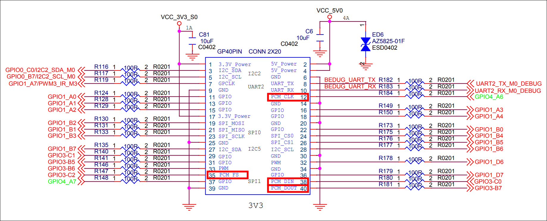
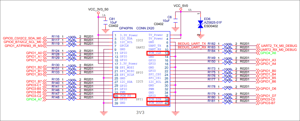
Hello friends, Has anyone here successfully activated the I2S pins for connecting a DAC? According to the official documentation, the PCM functionality should be available on physical pins 12 (GPIO4_A6), 35 (GPIO3_C2), 38 (GPIO3_C0), and 40 (GPIO3_B7) of the GPIO header. I've tried many options - in the DTS overlay I've enabled various I2S variants starting from "i2s0_8ch" up to "i2s9_8ch", including different "pinctrl" m[0-1] variants like "i2s1m0" or "i2s1m1", and alternatively "i2s2m0" or "i2s2m1", but I've never managed to get ALT3 mode on the mentioned pins (I assume I2S function = ALT3 mode). In certain combinations, I can at least achieve some half-working state where the system detects the sound card and it can be controlled (e.g., in alsamixer), but I've never managed to get any actual sound output. Has anyone managed to get I2S-DAC working on Orange Pi 5 MAX? I'm attaching the overlay I've been working with. Remember that I've tried all available i2s target combinations: /dts-v1/; /plugin/; / { compatible = "xunlong,orangepi-5-max", "rockchip,rk3588"; // Enable I2S fragment@0 { target = <&i2s1_8ch>; __overlay__ { status = "okay"; #address-cells = <1>; #size-cells = <0>; pinctrl-names = "default"; pinctrl-0 = <&i2s1m0_mclk &i2s1m0_lrck &i2s1m0_sclk &i2s1m0_sdo0 &i2s1m0_sdi0>; }; }; // Enable I2C fragment@1 { target = <&i2c2>; __overlay__ { status = "okay"; #address-cells = <1>; #size-cells = <0>; wm8960: wm8960@1a { compatible = "wlf,wm8960"; reg = <0x1a>; #sound-dai-cells = <0>; clocks = <&clk_fixed>; clock-names = "mclk"; wlf,shared-lrclk; }; }; }; // Define soundcard fragment@2 { target-path = "/"; __overlay__ { sound: sound { compatible = "simple-audio-card"; simple-audio-card,name = "WM8960 Audio"; simple-audio-card,format = "i2s"; simple-audio-card,bitclock-master = <&dailink0_cpu>; simple-audio-card,frame-master = <&dailink0_cpu>; simple-audio-card,widgets = "Speaker", "Speaker", "Headphone", "Headphone", "Microphone", "Mic"; simple-audio-card,routing = "Speaker", "SPK_LP", "Speaker", "SPK_LN", "Headphone", "HPOUTL", "Headphone", "HPOUTR", "IN1L", "Mic", "Mic", "Mic Bias"; simple-audio-card,cpu { sound-dai = <&i2s1_8ch>; dai-tdm-slot-num = <2>; dai-tdm-slot-width = <32>; }; dailink0_cpu: simple-audio-card,codec { sound-dai = <&wm8960>; }; }; }; }; // Define MCLK fragment@3 { target-path = "/"; __overlay__ { clk_fixed: clk_fixed { compatible = "fixed-clock"; #clock-cells = <0>; clock-frequency = <12288000>; // Typická MCLK pro WM8960 clock-output-names = "mclk"; }; }; }; };
-
I found the dts setting about "ethernet@5020000" was different between kernel 5.15.93 and kernel 6.1.47. We need to make sure the following things are correct: 1. Ethernet driver uses the correct clock/reset 2. GPIO reset can be pulled up 3. MDIO can correctly go to PHY 4. Pinmux correctly sets Ethernet pins #Kernnel 5.15.93-sunxi64 ethernet@5020000 { compatible = "allwinner,sun50i-h6-emac\0allwinner,sun50i-a64-emac"; syscon = <0x31>; reg = <0x5020000 0x10000>; interrupts = <0x00 0x0c 0x04>; interrupt-names = "macirq"; resets = <0x04 0x21>; reset-names = "stmmaceth"; clocks = <0x04 0x54>; clock-names = "stmmaceth"; status = "okay"; pinctrl-names = "default"; pinctrl-0 = <0x32>; phy-mode = "rgmii-id"; phy-handle = <0x33>; phy-supply = <0x34>; phy-io-supply = <0x35>; allwinner,rx-delay-ps = <0xc8>; allwinner,tx-delay-ps = <0xc8>; phandle = <0x78>; mdio { compatible = "snps,dwmac-mdio"; #address-cells = <0x01>; #size-cells = <0x00>; phandle = <0x79>; ethernet-phy@1 { compatible = "ethernet-phy-ieee802.3-c22"; reg = <0x01>; reset-gpios = <0x1f 0x03 0x0e 0x01>; reset-assert-us = <0x3a98>; reset-deassert-us = <0x9c40>; phandle = <0x33>; }; }; }; #Kernel 6.1.47-current-sunxi64 ethernet@5020000 { compatible = "allwinner,sun50i-h6-emac\0allwinner,sun50i-a64-emac"; syscon = <0x32>; reg = <0x5020000 0x10000>; interrupts = <0x00 0x0c 0x04>; interrupt-names = "macirq"; resets = <0x06 0x21>; reset-names = "stmmaceth"; clocks = <0x06 0x54>; clock-names = "stmmaceth"; status = "okay"; pinctrl-names = "default"; pinctrl-0 = <0x33>; phy-mode = "rgmii-id"; phy-handle = <0x34>; phy-supply = <0x2e>; phy-io-supply = <0x35>; allwinner,rx-delay-ps = <0xc8>; allwinner,tx-delay-ps = <0xc8>; phandle = <0x79>; mdio { compatible = "snps,dwmac-mdio"; #address-cells = <0x01>; #size-cells = <0x00>; phandle = <0x7a>; ethernet-phy@1 { compatible = "ethernet-phy-ieee802.3-c22"; reg = <0x01>; reset-gpios = <0x1e 0x03 0x0e 0x01>; reset-assert-us = <0x3a98>; reset-deassert-us = <0x9c40>; phandle = <0x34>; }; }; };
-
 Hi @Ed van den Enden, Checked a bit more on the internets and found that you have added the device overlay to your BanananaPi in the same manner as you have done on your RaspberryPi: dtoverlay=i2c-rtc,ds1307 On armbian you add overlays using: # armbian provided overlays overlays=usbhost2 usbhost3 i2c0 uart1 pps-gpio # user provided overlays user_overlays=rtc0-i2c-ds3231-rtc1-soc Also confirmed that boot.cmd indeed only expects to see user_overlays in the armbianEnv.txt and does not check for dtoverlay. You can check in /boot/dtb/overlay/ which armbian provided overlays are there, but for the i2c RTC you would need to add a user defined overlay. Safest bet would be to use the armbian-add-overlay tool that will compile (and check) then add the overlay to your armbianEnv.txt using the keywords that will make sure the overlay is used during boot. As mentioned before as well, you would need to have the device tree files handy for armbian-add-overlay to process them. These are .dts files and are human readable. The topic mentioned in the reply earlier has the two .dts device tree overlays that should also work for your case. Groetjes,
 -
 Indeed, the rtc_ds1307 is compatible with the ds3231 and removing pps-gpio w1-gpio did the errors disappear. The RTC module still doesn't work. 😭
 -
 I believe the rtc_ds1307 is compatible with the ds3231. You can check that with "modinfo rtc_ds1307" I don't know the hardware, can you check that you don't have pin conflicts? Do you need these overlays : "pps-gpio w1-gpio" ? If not, you might remove them from armbianEnv.txt, boot and check again.
 -
The below output with the RTC module taken off the BPI M2Z Further below I saw that there were some pin errors. (most probably nothing to do with this topic) https://paste.armbian.com/axoduwanuq [ 1.020506] usbcore: registered new interface driver usb-storage [ 1.022284] sun6i-rtc 1f00000.rtc: registered as rtc0 [ 1.022371] sun6i-rtc 1f00000.rtc: setting system clock to 1970-01-01T00:00:04 UTC (4) [ 1.023147] i2c_dev: i2c /dev entries driver [ 1.025025] sunxi-wdt 1c20ca0.watchdog: Watchdog enabled (timeout=16 sec, nowayout=0) [ 7.721526] sun8i-h3-pinctrl 1c20800.pinctrl: pin PD14 already requested by onewire@0; cannot claim for pps@0 [ 7.721577] sun8i-h3-pinctrl 1c20800.pinctrl: pin-110 (pps@0) status -22 [ 7.721597] sun8i-h3-pinctrl 1c20800.pinctrl: could not request pin 110 (PD14) from group PD14 on device 1c20800.pinctrl [ 7.721613] pps-gpio pps@0: Error applying setting, reverse things back
-
With these instructions, you may get UART5 in ttyS1 https://forum.armbian.com/topic/43718-orange-pi-zero-3-issues-with-gps-on-uart/ https://forum.armbian.com/topic/44034-using-gpio-ports-on-orangepi-zero3/#comment-201030
-
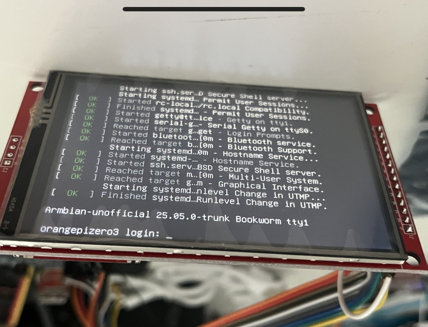
When I start from scratch with TheGoing repo, linux 6.13.7, I apply my DTS, copy my firmware, and I get this DT (snipped in the area that counts) And the LCD works. And when I start from scratch from the Armbian repo, linux 6.13.11, I apply my DTS, copy my firmware, and get this Device Tree: But the GPIO pins PC7 and PC14 appear unclaimed (as seen in previous post), and the LCD remains white. The linux build configs are practically the same (side in 6.13.11 has the error in SPI configuration) I found that the TheGoing repo has a two less patches applied... the zero 2w seems more relevant IMPORTANT: I just added "-" before "patches.armbian/arm64-dts-sun50i-h618-orangepi-zero2w-Add-missing-nodes.patch" in the: build/patch/kernel/archive/sunxi-6.13/series.conf file, and I finally have the ili9488 LCD working with my ili9488-ads7846 DTS My SBC is the OrangePiZero 3, and I select that specific SBC in the menuconfigs after starting "./compile.sh"
-
Help! My DTS, which used to work with 6.13 and 6.12 from the unofficial repo's from NickA and Going... are not working in the official armbian linux 6.13 This is an issue of not owning the DC and RESET pins, as seen in PC7 and PC14 need to show this: pin 71 (PC7): GPIO 300b000.pinctrl:71 pin 78 (PC14): GPIO 300b000.pinctrl:78 dmesg shows this error: $ dmesg|grep spi [ 1.911366] sun6i-spi 5010000.spi: Error applying setting, reverse things back [ 1.911650] sun6i-spi 5011000.spi: Error applying setting, reverse things back [ 1.917726] sun6i-spi 5010000.spi: Error applying setting, reverse things back [ 1.918005] sun6i-spi 5011000.spi: Error applying setting, reverse things back ... The DTS I used is: I think anyone with Linux 6.13 (armbian official) can try this DTS without an LCD connected to the orange pi zero 3... at this time, I only need that the PC7 and PC14 are owned by the SPI driver.