Search the Community
Showing results for '"usb power"'.
Found 20 results
-
 Hello, I'm trying to get Armbian (Ubuntu 24.10 XFCE Desktop) running on a retro game stick device with the following specs: CPU: Amlogic S905M RAM: 8 GB Samsung (2x K4B4G1646B) Storage: Samsung 128 GB MicroSD (new, flashed via balenaEtcher) Ports: 1x USB-A, 1x MicroSD slot, 1x MicroUSB power (possibly supports OTG), 1x HDMI male output Original firmware: EmuELEC (working fine from factory SD card) What I tried: Flashed Armbian Ubuntu 24.10 (from debmfc GitHub) to the SD card Tried box=s905_generic in the config file Replaced dtb.img with several DTBs, including: meson-gxbb-p200.dtb meson-gxbb-p201.dtb meson-gxbb-xtmqbox.dtb Performed toothpick method to boot from SD card Green LED turns on, but: No HDMI output CPU stays cold, no signs of booting USB devices receive no power No blinking, no UART logs (I don’t have serial access yet) It feels like the CPU doesn’t even begin to initialize Linux – maybe it doesn't load the u-boot from the SD at all? Any idea what else I can try? Is there a minimal verified Armbian image known to boot on S905M-based TV sticks? Do I need to trigger multiboot somehow? Could this be a special bootloader variant? Could I use the original EmuELEC SD and inject Armbian files into it? Any help or known working image would be greatly appreciated. Thanks in advance!
 -
 Hi, I've come from Joshua's 24.04 Server build. I was concerned that the support was dropping off as he's having a well deserved break. I've installed the latest Server build from here. https://dl.armbian.com/orangepi5-plus/Noble_current_server-kisak Works fine, have moved it to EMMC and removed the SD card. I use a USB power meter to see how much juice it uses. I noticed this build uses about 20 to 25% more when idle or under load compared to Josh's 6.1 kernel build. I am suspecting 6.12 has enabled more hardware in the OPi5+ and this is the reason. Is there a way to disable some of the HW to lower the idle power usage? On average it uses 5w on idle. Thanks. Loving the Armbian build.
 -
 The SD card problem is ruled out since I tested another system on the same card and there is no problem it works perfectly example image, 2022-04-17-ubuntu-16.04-mate-desktop-mpv-1080p-bpi-m1-m1p-r1-sd-emmc.img . Other systems like lakkaTv also work, I tried with several USB power adapters and it only generates problems with modern versions of Armbian
 -
I only test on my OdroidC2 so this find may affect more. As repeatedly mentioned, the C2 has usb detect issues. For us, a main culprit not discussed yet is the default kernel config. Having both: CONFIG_USB_EHCI_TT_NEWSCHED=Y CONFIG_USB_OHCI_HCD=Y For USB1.1, these should be one or the other, never both. Mainline has: CONFIG_USB_OHCI_HCD=Y and CONFIG_USB_EHCI_TT_NEWSCHED is not set. For the OdroidC2, CONFIG_USB_OHCI_HCD=N is proper. As it has no OHCI and USB2 handles that for us. Forcing the USB power on state has helped workaround this issue, by keeping the driver tied to the device in the kernel.
-
 I used this image as base and from there did in-place full-upgrade: It used to lock-up with a kernel crash after 2 - 3 days, kernel 6.6.44 till 6.6.75. I have no HDMI connected anymore, only serial console cable, SD-card, microUSB power, RJ45 and SATA 8T HDD. Now with kernel 6.12.20-current-sunxi uptime already 6 days. I have radically modified partition setup, use Btrfs for rootfs, I do not use Armbian initial repartition scripts, that seems to be the point where your M1 fails. You need serial console cable and post clear text output where it fail. Still then, it might be too complicated to or time consuming fix. You could prepare/create/build a new own image using Armbian build. Or just stick to that older working image. It could be that the GUI drivers like it was in older kernels is dropped after 5.10 kernels or so, that happens to older hardware unfortunately. What is the kernel version where it still does work?
 -
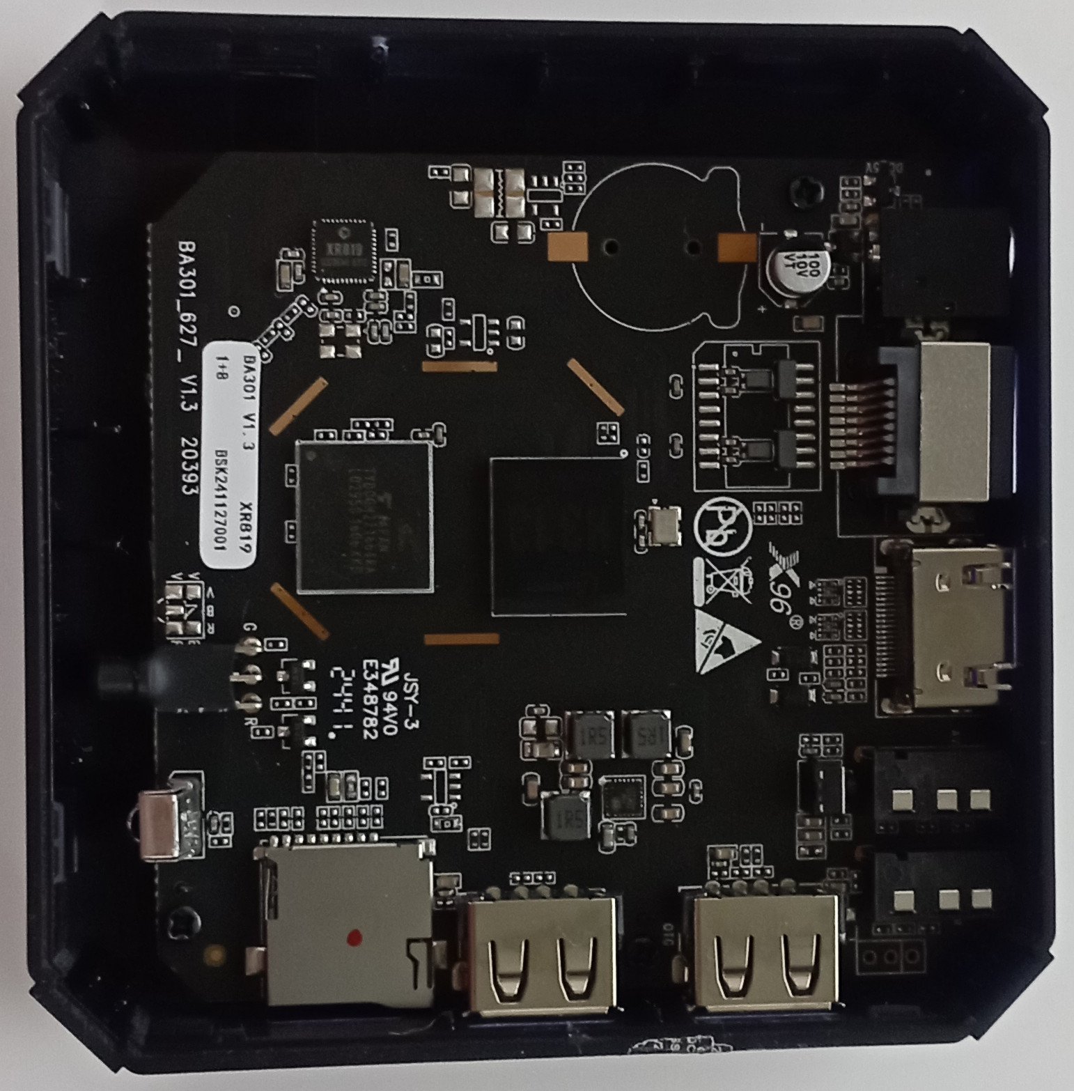
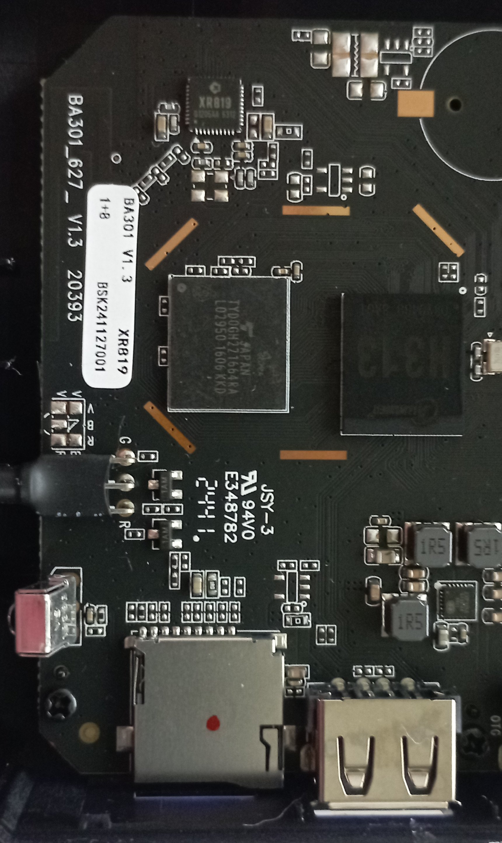
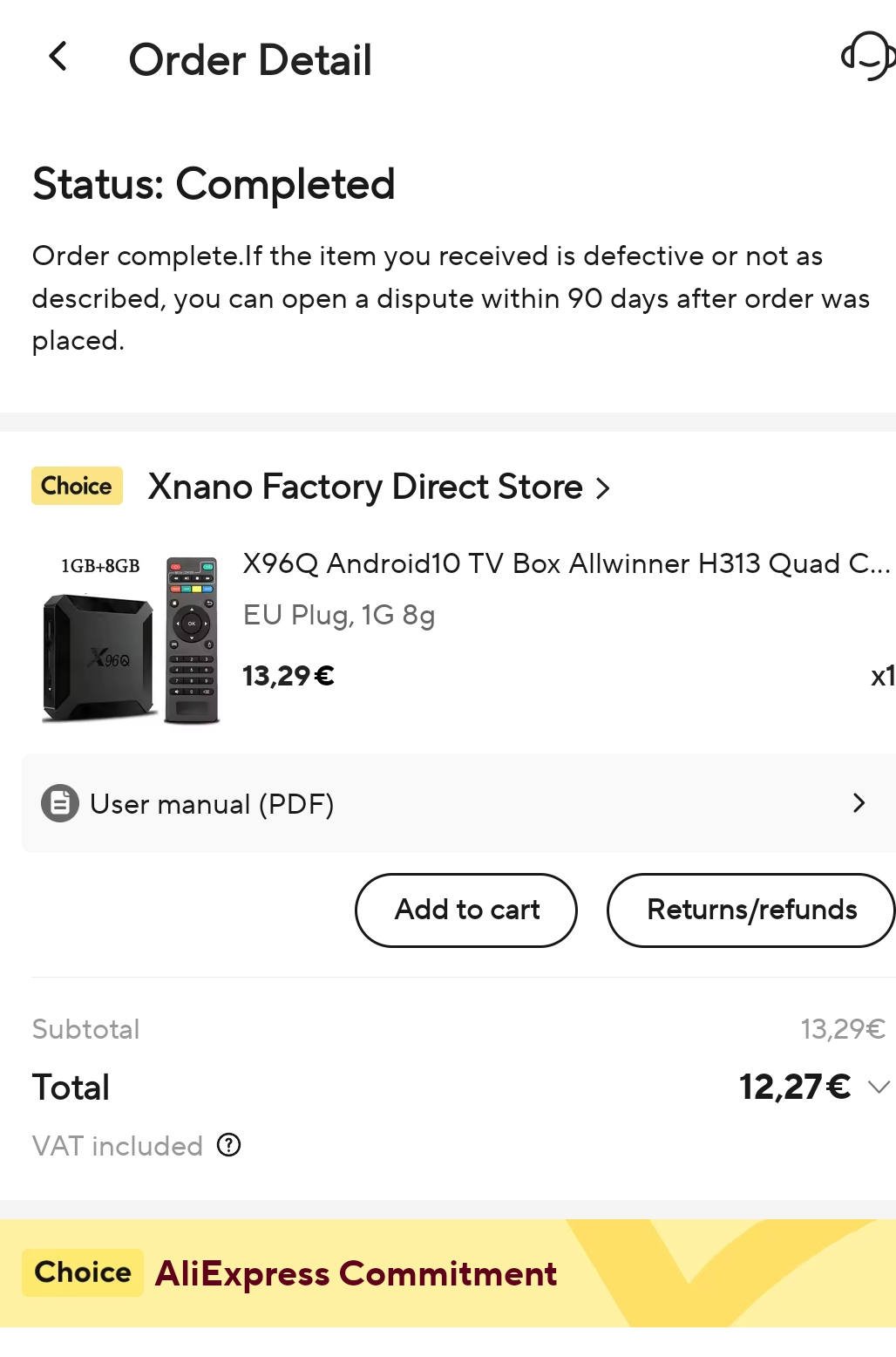
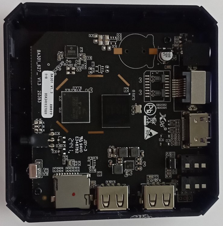
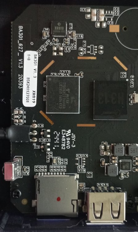
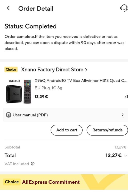
@Kmani no armbian image worked for me, it only worked MiniArch lpddr3 posted in this thread. I tried armbian image from https://github.com/sicXnull/armbian-build/tree/X96Q-TVBOX-LPDDR3 with no luck, nothing happened, box started with internal nand ignoring the armbian flashed in microsd, I dont know if I did something wrong, but MiniArch lpddr3 image worked, without ethernet but with hdmi working, I plugged a USB ethernet and it worked fine. I didnt touch a byte of internal nand, if you want some file from factory firmware tell me and I'll try to extract it. I opened the box and the board version seems to be 1.3. The box was bought in a bundle deal of aliexpress (buying three things together). Btw I recommend a DC 5.5*2.1 to USB cable adaptor, these boxes work perfectly powered by a USB cable (usb power banks and so on).
-
.thumb.jpg.d12ff4661cda8bcd4c6c766fa549b1b9.jpg)
Tons of GPT errors on boot when USB drive is connected
Z11ntal33r replied to dnwhoop02's topic in Odroid N2/N2+
I just want to say, c0rnelius, you are a lifesaver! I’ve spent several hours trying to figure out this issue, and it’s reassuring to see I’m not the only one dealing with it. This problem must be more common than it seems. I initially thought it was related to power management, as the external drives might be drawing too much power. In my case, I tried countless methods to disable USB power management and other tweaks, but it turns out the simple custom boot file was the ultimate solution! For reference, I’m running v24.11.1 on an Odroid N2 with Armbian Linux 6.6.63-current-meson64 Update This is a more widely issue it seems given there are other releated threads -

La Frite wont boot armbian, kernel panic etc.
bedahtpro replied to bedahtpro's topic in Libre La Frite
Thanks for all the help youve given me, i really appreciate it, I thought maybe this could be it, I dont have a USB power meter unfortunetly but i do have a computer PSU ATX Breakout board which allows me to plug in a PC PSU with the atx connector and i then get 6x USB ports, this is a pcb and it is as dumb as it gets, Outputs 5V 2.0A at all ports, only usb a ports. I really thought it could work but no, same issue now as always, Unfortunetly Libre Computer is not helping at all and not even responding to me so i will have to give up on this board and try to return it or make a warranty claim. The problem is not with the storage, not with the power and not with the images, so the only option left is that there is something wrong with the board. I usually see the messge "Failed to change CPU frequency -5" right before it stops so perhaps there is something wrong with the cpu. I have purchased one Radxa Rock 2F 2GB and one Orange Pi Zero 3 1GB. Hoping i will have better luck with these boards. -

La Frite wont boot armbian, kernel panic etc.
TonyMac32 replied to bedahtpro's topic in Libre La Frite
You don't have any "dumb" power supplies? Any USB-type -C style charger will limit to 450 or 900 mA without a "smart" device attached to it, irrespective of it's rating. (it requires a matched supply/cable/endpoint configuration to get 5V 1.5 or 3 A) *Most* QC- compatible (USB A output) will also limit the current unless they detect the correct QC-style resistances on the endpoint. You wouldn't happen to have a USB power meter on hand to see if these supplies are throttling the USB-A based on the fact the device has no "smart" charging built into it? I just measured mine and with keyboard, HDMI and network attached I broke 600 mA peak. If the supply had throttled to 450 mA it would have crashed right after loading the kernel. Otherwise I think you need to talk to LC and see if they can debug the issue you're having. -
I did a lot of power consumption tests with my NanoPi R6C and noticed something strange when switching from kernel 5.10.110 to kernel 5.10.160. Hardware NanoPi R6C 4GB 32GB Sandisk High Endurance microSD Card Ugreen 18W USB Power Supply Software Armbian 23.5.1 Nanopi-r6s bookworm Default settings (only changing fdtfile=rockchip/rk3588s-nanopi-r6s.dtb to fdtfile=rockchip/rk3588s-nanopi-r6c.dtb in /boot/armbianEnv.txt) Switching between legacy 5.10.160 and legacy 5.10.110 kernels with armbian-config With just 1Gbit Ethernet and the power supply connected in idle (measured at wall): kernel 5.10.110: 0,92W kernel 5.10.160: 1,21W I also tested different M.2 SSD, with ASPM L1 enabled/disabled, HDMI and USB devices connected/not connected. I even tried different usb power supply. In every case the power consumption with kernel 5.10.160 is higher with no apparent benefit. You could argue that it is not a big difference but when running the system from a battery it is! What is causing this increased power consumption? I tried to run a lot of commands to find the difference between the 2 kernels but could not find a significant one. WinDiff between the 2 kernels:
-

OrangePi Zero LTS ili9341 TFT LCD (and later OrangePi Zero 3)
robertoj replied to robertoj's topic in Allwinner sunxi
It turned out that my USB power cable was too long... I replaced it with the previous short one and I am back in business. I am experimenting with NOT USING CS. Good progress: In the DTS, comment out with "/*" the line cs-gpios = <&pio 0 13 0>; /* PA13 chip select */ Also, change this line num-chipselects = <1>; to <0> Previous result of: sudo cat /sys/kernel/debug/pinctrl/1c20800.pinctrl/pinmux-pins ... New result, with NO CS configuration: ... ... ^ with my next steps, I hope to verify that PA13 is available for other things It plays an h264 file with no hiccups mplayer -vo fbdev2:/dev/fb0 mj_remember_time.mp4 -
 probably a post bragging of my christmas gifts, but mostly just documentation because it really confused and stumbled me from the get go so, my setup was powering tinkerboard (the first revision, without the new fangled eMMCs) via GPIO because it confused the hell out of me how to power this beast. this was powered through the XL4015 buck converter 12.1/12.2 V on input, with ammeter and voltmeter included on the board. (the board was current limited to 5A, because why not? the rk808 is 6A tops) ok from the get go the board powers (not load tested, just power through and run kodi-gbm UI) from 3.4V to 6.2V. undervolting or overvolting it doesnt shuts itself down (no red light), then bringing back to operating voltages boots the board up also take not that operating voltages for RK808 was 2.7V to 5.5V. the missing 0.7V was probably the diode drop people are talking about. maybe? without a multimeter (only using the power supply's voltmeter-ammeter) i can't check it that much. but i'm fine that it has wide range of operating voltages. on all observed voltages, 3A seems to be the max current. it needs to be sustained though. also full load without peripherals (and HDMI, HDMI seems to be active than passive) is observed 2.3-2.5A. booting up the board needs about 0.7A to keep on going this would probably contradict as well the "increase voltage to 5.25 or smthing" given that no matter how many volts you put into it, it would only use 3A. weirdly (since this contradicts the block schematics from tinkerboard), #1 and #2 are observed in both USB and GPIO with no difference (significant or not) under load. it's weird since 3.1. if USB lines were protected, there should be a diode drop *only* on USB lines. but this was seen on GPIO as well. 3.2. some claims microUSB only has max 2.5A but this is not seen in this case: the setup sustained 2.7A going 2.9A. also, powering both GPIO and USB with the same power block doesnt seem to affect stability at all (still hard limits at 3A.) so with that, there are few suggestions for powering the board as well (and minor observations. opinionated parts ahead) people talking about overvolting or undervolting the power rails doesnt really help at all at slightest. it'll still top at 3A. what overvolting could help were powering via USB peripherals, but i wouldnt recommend it plugging straight given the fact that 2.5A on full load? you only have 0.5A to spare on heavy load. get a usb y splitter (tape over the USB power lines to the board. idk why but i have usb resets whenever i dont have them. then again plugging a hard drive in there shouldnt be happening in the first place) the raspberry pi 3B+ adaptor (5.25V, 2.5A)? good enough actually! as long as it can deliver 5V across the device, AND as long as you dont have power heavy devices on it. it doesnt matter that much so long as your USB cable can handle phone-charger level of amps. rk3288 was designed with mobile phones in mind. it'll always power at 3.7V. i always having issues when im using a cable that can only do 0.5A across it. no can do. probably for me, but this is why you dont need to be hung with the minor details. starting from this, im wracking my brain around if tinkerboard was sensitive to power drops (like 5.1v or 5.2v would show stability improvements) but nope! just chuck it right in, it'll be fine. just check your connections and stuff. powering through the GPIO pins is recommended of course, but it's an overkill. probably the reason for it was most USB chargers only go 2A max and that would underpower the tinkerboard, doing boot loops instead of starting correctly. then again YMMV: my place has 3A or 5A chargers everywhere. and with the introduction and interests of fast chargers, you'll find chargers (and cables) that can deliver more than you expect. on sidenote on powering through the GPIO: PLEASE GET YOUR GAUGES RIGHT. i powered it via the ATX FDD (remember those?) connector, with 12V pin removed. it turns out for some reason its max current is 1A and its just thin flimsy as hell. get a thicker wire. it didnt drop the current (thankfully) but the wire became so warm to touch, it's weird. i wouldnt wanna run this on full load. at least i didnt get burned wires. cooling fan helps a lot also you cant bypass that 3A limit. that's 3A total, both GPIO and USB inputs. even powering both USB and GPIO (like that one person suggested) doesnt really do anything. you wouldnt get that much power in, but at least you can protect your wires? which is weird since block schematics shows GPIO and USB has different lines? so it should have different protections and stuff. a multimeter can help see if those inputs are shorted (GPIO vs microUSB vs peripherals) but i dont have one at the moment i would also like to measure the voltage across the peripherals if any load situations will lead to undervolting the outputs, but i dont have a USB tester at the moment. RK808 seems to be programmable but interfacing with it is outside of my skill set. any help would do i hope this post helps everyone well. no one uses these boards anymore except for niche use cases but i still enjoy it. i hope in the future i can get myself a huge NAS server with an RK3588S on it. kinda lonely to be honest
 -
The USB power has been a growing issue with my C2 for years now. To have the board use the SSD through a USB/SATA adapter, I now have to power the adapter (which has a Y cable) from a neighbour board. It used to work long time ago without the other board "help". So there is probably a weakening component on my C2. Right now the voltage drops between the +5V barrel alim centre, and USB connectors' 5V. I see no rationale in this. My C2 is now decommissioned (I bought a OPi 3 LTS instead). So I will try to to solder a wire under the board to have the incoming 5V straight to the USB ports. It should not be worse than the Y USB cable bringing the 5V from the neighbour board.
-

USB and LAN randomly disconnects. any help? or ideas to replicate it?
crr replied to xAda's topic in Tinkerboard
I'm using Tinkerboard with USB connected SATA HDD for 5 years as 24/7 server and had no similar issues with powering. The device is powered by dual USB socket power supply (1x USB to power TB, 1xUSB to power HDD via Y-USB cable). I would start with metering voltage or plugging cheap voltage monitor between power supply and TB. Try also USB power supply providing 5.2V instead of 5.0V It should also work when power is only provided to TB USB output (from external powered USB hub) I had similar issues with Raspberry Pi 3B - with similar configuration (USB 1xHDD 2,5") and main indicator of failure was undervoltage - (vgencmd indicated ) and changing power supply did not help. The only solution I've found for it was to programatically power cycle Raspberry Pi built-in USB hub every time when HDD was not available. -
Recover OrangePi 5 Plus Download: https://drive.google.com/drive/folders/19SMZHj1Y8l_Vvr6_SMDHYdJHi41hMgsI Press and hold the MASKROM button, then plug in USB power and release the MASKROM button Open a terminal in Linux and install "rkdeveloptool" *Note, I saved all the files in that URL to /home/$USER/opi5plus then "cd opi5plus" | use "sudo rkdeveloptool ld" to see if your device can be seen (plug in USB cable from PC to the USB-C connector opposite the power). opi5plus$ sudo rkdeveloptool db MiniLoaderAll.bin Downloading bootloader succeeded. opi5plus$ sudo rkdeveloptool ul MiniLoaderAll.bin Upgrading loader succeeded. opi5plus$ sudo rkdeveloptool td Test Device OK. opi5plus$ sudo rkdeveloptool rd Reset Device OK. Make sure you have a freshly baked SD card installed with your Linux flavor of choice then power off, install the SD card and boot up!
-

ORANGE PI PLUS 2 doesn't recognize keyboard or mouse
nicolho replied to ssamuelm's topic in Allwinner sunxi
USB won't be enabled automatically by those "Plus 2E" images, at least because it looks like their bootloader's device tree (FTD) doesn't enable the USB1-VBUS switch that powers the Plus/Plus2 on-board hub, and also directly feeds the USB power line to one pair of USB ports. The later wouldn't provide any current, unlike the other pair which is always powered regardless of any software settings. Then a simple way to know if this is related would be to find a USB device that can turn-on in some way (like lighting a led) even when only plugged in a USB charger, and test if it also turns on as well plugged into one of the USB port pair, but stays off with the other. -
Hello, BPi M5 freezes after a couple of hours running randomly. - use armbian Armbian 23.02 Bullseye ( 6.1.11) - same effects with Armbian Bookworm CLI kernels 6.1.x 6.2.x Now tried Sinovip Ubuntu (kernel 4.9.x ) aud it is running for days ! form their Homepage armbian from Sinovip page link also freezes... Why Armbian ( or Kernel 6.x ?) freezing . also found that USB power (for my data-USB-HDD) will be switched OFF during boot mostly . tried uhiubctl with permanant switch ON .. -> starts better - can ust USB-HDD in fstab ... but System freezes (include: USB no longer with power ) Is there any script to be change during boot or depends it to kernel ? hidden powersave options ? I want use it for a 24/7 running System (nextcloud) - any ideas ? g.l Fred
-
I've tried a few images of the latest builds. None of them start. Odroid starts to power the screen and I see blinking lights, but screen goes dark and it seems to cycle like this. I use USB power for it and a powered hub (so basically no power output to USB dongles, etc.)
-
So looking at my aft section print I discovered some issues. I'm working on the CAD drawing a bit today I may or may not be done and update the GIT repo with updated CAD files today. I am also adding a wire retainment setup for the power wire with a filler peace. That will allow the usb power cable to go in the back and be neat.
-
weird "bumping" this old question but here are some of my findings, just quick answer (my tinkerboard runs on 2x USB-SATA HDD's, 1x 2TB, 1x 500gb, and 1x 1.5TB external hard drive) 1. flash firmware on your USB-SATA. it shuts down every 10 minutes or so, depending on the chip, but other firmware dont have those issues (eg, those HDD cloners). check your SATA-USB controller for reflashing. this is left as an exercise to the reader. 2. remember that tinkerboard isnt 4x usb but rather 2x USB device, 1 lane is reserved for the audio controller and the other lane is split to a Genesys 4USB hub controller. since this is USB2.0, you're stuck at 480Mbps, around 60MB/s transfer rates. since it's half-duplex, it's halved to 30MB/s on the hub alone. expect a max throughput of 30MB/s shared. real life performance may vary: i sometimes get full 30MB/s on one device, sometimes, all devices are just the slow. depends on your use case, 30MB/s is just *slow* that's pretty much it about my experiences on the device. now i'm getting a used 500GB HDD running e2fsck. i hope it works well, for 2 days it seems okay. this is while one HDD runs tar while the other does downloading. also be wary of power consumption: 3A on the whole device (take note without peripherals, tinkerboard runs at ~1A on idle and ~2.5A on full load) . go beyond that will cause instability (either boot issues, or in my case USB hub stops working.) i wont recommend using a hub (no issue in power, but slow-downs are a real pain in the butt) but instead those USB-Y splitters that split the device's power. use a separate USB power brick to power the devices alone (i taped my power lines going on the device's side, just to be safe.)