Search the Community
Showing results for 'gpio'.
-

armbian-build, dts patch, can't find file to patch at input line 9...
going replied to Murat Demirtas's topic in Beginners
To do this, you will need to open two sessions in the terminal. The test here is my configuration file 1 session ~/armbian$ ./compile.sh test kernel-patch ...... # build system printed: [✨] Starting [ interactive patching process for kernel ] [🌱] Creating commit to start from clean source [🌱] Patches will be created [ with the following maintainer information ] [🌱] MAINTAINER (Real name): [ The-going ] [🌱] MAINTAINERMAIL (Email): [ 48602507+The-going@users.noreply.github.com ] [🌿] If those are not correct, set them in your environment, command line, or config file and restart the process [🚸] Make your changes in this directory: [ /home/leo/armbian/cache/sources/linux-kernel-worktree/6.13__sunxi64__arm64 ] [🚸] Press <ENTER> after you are done [ editing files in /home/leo/armbian/cache/sources/linux-kernel-worktree/6.13__sunxi64__arm64 ] Press ENTER to show a preview of your patch, or type 'stop' to stop patching... The build system will apply all the patches and make a commit that will include all the changes. Leave this session alone. In the second session, you make your changes and record the results. 2 session leo@armbuild:~/armbian$ cd /home/leo/armbian/cache/sources/linux-kernel-worktree/6.13__sunxi64__arm64 ### open root session leo@armbuild:~/armbian/cache/sources/linux-kernel-worktree/6.13__sunxi64__arm64$ sudo su root@armbuild:/home/leo/armbian/cache/sources/linux-kernel-worktree/6.13__sunxi64__arm64# ls arch/arm64/boot/dts/rockchip/rk3399-* linux-kernel-worktree/6.13__sunxi64__arm64# nano arch/arm64/boot/dts/rockchip/rk3399-orangepi.dts linux-kernel-worktree/6.13__sunxi64__arm64# git add --all linux-kernel-worktree/6.13__sunxi64__arm64# git commit -m "Add a comment" ###close root session: linux-kernel-worktree/6.13__sunxi64__arm64# exit linux-kernel-worktree/6.13__sunxi64__arm64$ git format-patch -1 -o /home/leo/armbian/userpatches/ /home/leo/armbian/userpatches/0001-Add-a-comment.patch linux-kernel-worktree/6.13__sunxi64__arm64$ cat /home/leo/armbian/userpatches/0001-Add-a-comment.patch From 4dad6a3fa967235ea7eef35f81733bdafd806b53 Mon Sep 17 00:00:00 2001 From: The-going <48602507+The-going@users.noreply.github.com> Date: Tue, 18 Mar 2025 12:54:11 +0000 Subject: [PATCH] Add a comment --- arch/arm64/boot/dts/rockchip/rk3399-orangepi.dts | 1 + 1 file changed, 1 insertion(+) diff --git a/arch/arm64/boot/dts/rockchip/rk3399-orangepi.dts b/arch/arm64/boot/dts/rockchip/rk3399-orangepi.dts index 2ddd4da15..29eec7e65 100644 --- a/arch/arm64/boot/dts/rockchip/rk3399-orangepi.dts +++ b/arch/arm64/boot/dts/rockchip/rk3399-orangepi.dts @@ -78,6 +78,7 @@ keys: gpio-keys { compatible = "gpio-keys"; autorepeat; + /* key-power */ key-power { debounce-interval = <100>; gpios = <&gpio0 RK_PA5 GPIO_ACTIVE_LOW>; -- 2.34.1 What should I do with the first session? Decide for yourself!! -

Armbian for custom SKIPR on TwoTrees SK1
Mechano replied to Mechano's topic in Framework and userspace feature requests
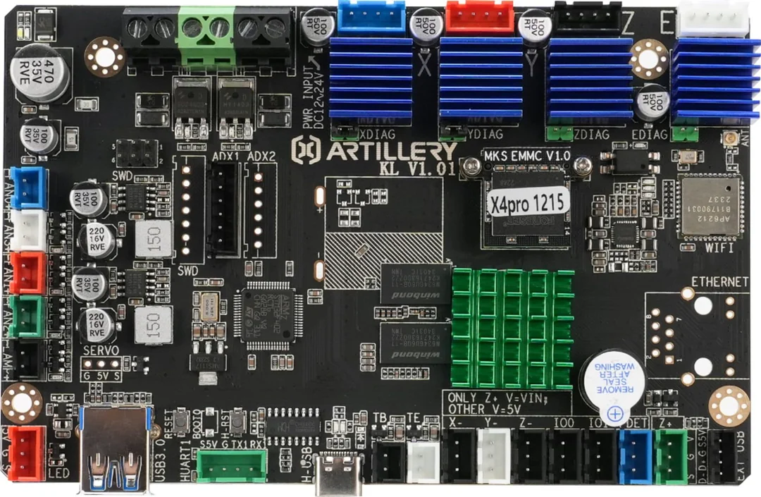
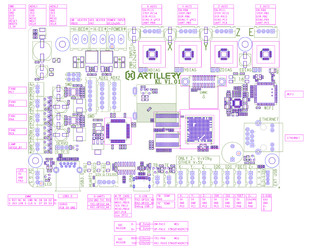
I had success on installing this Armbian for SKIPR also on Artillery Sidewinder X4 Plus machine. The whole X4 lineup uses this custom SKIPR board. In the Sidewinder X4 board there's no Ethernet port, so to configure WiFi you have 3 solutions: solder the Ethernet header and connect cable network just to login and configure WiFi, use an USB-to-Ethernet dongle compatible with Linux, use service USB-C port with terminal emulation. Always follow Maxim's instruction on take .dtb file from stock image and apply to Armbian distribution. The Armbian has everything to configure the stock ADXL345 module provided by Artillery just add into /boot/armbianENV.txt the following lines to activate GPIO thru spidev: overlays=rk3328-spi-spidev param_spidev_spi_bus=0 I'm pretty sure the Armbian for SKIPR can be installed also onto Kingroon KP3S Pro V2 and KLP1, and Anycubic Neptune 4 family printers because they use same SKIPR custom board.

-
Armbian 6.6.16-sunxi64 (bookworm) on NanoPi NEO2 NanoHatOLED fails: - GPIO devices are missing; 2024-03-29 23:04:55 root@M-DNS:~# uname -a Linux M-DNS 6.6.16-current-sunxi64 #2 SMP Fri Feb 23 08:25:28 UTC 2024 aarch64 GNU/Linux Seems regression of earlier issue that had been solved: Would appreciate as GPIO will restored in kernel.
-
 Hardware: Banana pi M2 Zero OS Armbian_community_25.5.0-trunk.185_Bananapim2zero_bookworm_current_6.6.75_minimal pyGPIO - A 'more general' python GPIO library from "chwe". Question: Could the below python script work for a safe "shutdown" of the MBI M2Z? _____________________________________________________________________________ #!/usr/bin/python # shutdown/reboot Banana Pi M2 Zero with pushbutton from pyGPIO.gpio import gpio, connector from subprocess import call from datetime import datetime import time # Initialize GPIO gpio.init() # Pushbutton connected to this GPIO pin shutdownPin = connector.GPIOp11 # Adjust based on your wiring # If button pressed for at least this long, shut down. If less, reboot. shutdownMinSeconds = 3 # Button debounce time in seconds debounceSeconds = 0.1 # Set up the GPIO pin as input with pull-up resistor gpio.setcfg(shutdownPin, gpio.INPUT) gpio.pullup(shutdownPin, gpio.PULLUP) buttonPressedTime = None def buttonStateChanged(pin): global buttonPressedTime if gpio.input(pin) == gpio.LOW: # Button is down (active low) if buttonPressedTime is None: buttonPressedTime = datetime.now() else: # Button is up if buttonPressedTime is not None: elapsed = (datetime.now() - buttonPressedTime).total_seconds() buttonPressedTime = None if elapsed >= shutdownMinSeconds: # Button pressed for more than specified time, shutdown call(['shutdown', '-h', 'now'], shell=False) # Uncomment the following lines if you want to enable reboot functionality # elif elapsed >= debounceSeconds: # # Button pressed for a shorter time, reboot # call(['shutdown', '-r', 'now'], shell=False) # Subscribe to button presses gpio.set_irq(shutdownPin, gpio.BOTH, buttonStateChanged) while True: # Sleep to reduce unnecessary CPU usage time.sleep(5)
 -
It is common for tv boxes that some devices don't work out of the box. Tv boxes are not officially supported and will never be officially supported in armbian mainly for the reason they carry wildly different hardware and it is not feasible to give any kind of official support, hence it is totally a community effort. The reason rk3318-config does not show any wifi chip is that the wifi chip is either connected to a different mmc bus, or the "power on" gpio pin is the wrong one. Inspection of the device tree from the original firmware will surely clarify what is going on. Your particular board (X88 PRO is known to have the wifi chip on the "alternative" sdmmc_ext bus. In your case you have to run rk3318-config for a first time, configure the board with led-conf2, reboot, run again rk3318-config (this time it should show the wifi vendor and device IDs), let it configure the proper device tree overlay, reboot again and you should finally be able to see the wifi adapter. About the ethernet problem, I see NO-CARRIER: either the cable is not connected properly or the ethernet port is faulty. dmesg log is always very appreciated for debugging.
-
The Linux kernel is not detecting the WiFi card then its need the power being enabled by one GPIO from the system. Try other LED / board config in rk3318-config and also look in the head of it if its showing if the system have detecting some card (your screenshot its written: Wifi device: Not available) after doing the change and rebooting the device (some config can making the device not booting at all !!).
-
Hi, I am new to Armbian, and I don't know how to control VIM3's GPIOs. Can someone help me please? I have Armbian bookworm 24.5.1, kernel 6.6.32-current-meson. Thank you!
-
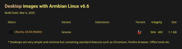
@robertoj I did not verify that it's hardware acceleration, but i assume it is because the playback quality is very acceptable. Also, the Android OS that comes on the EMMC could do hardware accelerated mp4 decoding. Even more, the Kickpi website provides a download link to a premade Ubuntu 24.04 image, but the performance is miserable compared to this Armbian, and it's on kernel 5.x or something. yes, that's all as it is from the desktop-armbian image. Nothing installed separately besides neofetch in that photo. this is what i used. (well not the March 6 build, it would have been one of the Feb 2025 ones) Also, keep in mind, i don't know it's exact power requirements - I have an Anker 200w USB C charger with 2 USB-A slots and 4 USB-C slots. So i power my Kickpi off one of the USB-C slots. It is happy with that. In armbian_zram_config, I have ZRAM_PERCENTAGE=30 otherwise it could crash/power-off while compiling bigger programs. I don't use the gpio or video decoding. I just use it for internet browsing, email, some retro emulators
-

Orange PI Zero 2w TFT capacitive touch screen ST7796
robertoj replied to Miguel González's topic in Allwinner sunxi
Try it with the ili9486 and ili9488 DTS we have made here: https://forum.armbian.com/topic/46824-orange-pi-zero-3-ili9486-tft-lcd/ https://forum.armbian.com/topic/47971-driving-the-ili9488-lcd-40-inch-cheap-chinese-clone/ For the gpio inside the DTS, it is only enough to know the port letter and pin number (you don't need the GPIO number and WPI) -

Help wanted to test a new OpenVFD alternative
Mark Waples replied to Jean-Francois Lessard's topic in Amlogic meson
Hi Jean-Francois, Yes I can confirm that all the leds are working correctly I used the overlay method so made the changes and then re-compiled transpeed-8k618-t-allwinner-h6.dtso In the tm16xx-display/devices folder make transpeed-8k618-t-allwinner-h6.dtbo cp release/transpeed-8k618-t-allwinner-h6.dtbo /boot/overlay-user/tm16xx.dtbo Reboot. New file contents: /dts-v1/; /plugin/; #include <dt-bindings/gpio/gpio.h> #include <dt-bindings/leds/common.h> &{/} { display-client { compatible = "i2c-gpio"; sda-gpios = <&pio 8 12 (GPIO_ACTIVE_HIGH|GPIO_OPEN_DRAIN)>; /* PI12 */ scl-gpios = <&pio 8 11 (GPIO_ACTIVE_HIGH|GPIO_OPEN_DRAIN)>; /* PI11 */ i2c-gpio,delay-us = <5>; #address-cells = <1>; #size-cells = <0>; display-controller@24 { compatible = "fdhisi,fd650"; reg = <0x24>; tm16xx,digits = [00 01 02 03]; tm16xx,segment-mapping = [03 04 05 00 01 02 06]; #address-cells = <2>; #size-cells = <0>; led@0,7 { reg = <0 7>; function = "wlan"; }; led@1,7 { reg = <1 7>; function = "lan"; }; led@2,7 { reg = <2 7>; function = "colon"; }; led@3,7 { reg = <3 7>; function = "usb"; }; }; }; }; Very happy - I just couldn't get it to work using openvfd. Maybe I needed to add the leds in the dts file to make openvfd? Anyway it's working so I am leaving it as is. Thank you so much!! -
I'm using the gpio cli. nothing else worked for me
-
Can you try other armbian images (i always use minimal), and self-built armbian image? Can you change USB cable? Powering with the 0V-5V pins in the GPIO pins?
-
I have question. OZPI v3 has support for hardware DS18B20 thermal sensor via w1-gpio ? In armbian-config when we got to the “system” section and select “Hardware” is not existing w1-gpio or OZPI v3 has not support for w1-gpio hardware ? Does not work because there is no device tree file (in the /boot/dtb/allwinner/) and we need to create it ??? like for OZPI v2 ?: 1. Create text file "sun50i-h616-w1-gpio.dts" /dts-v1/; / { compatible = "xunlong,orangepi-zero2\0allwinner,sun50i-h616"; fragment@0 { target = <0xffffffff>; __overlay__ { w1_pins { pins = "PC9"; function = "gpio_in"; phandle = <0x01>; }; }; }; fragment@1 { target-path = [2f 00]; __overlay__ { onewire@0 { compatible = "w1-gpio"; pinctrl-names = "default"; pinctrl-0 = <0x01>; gpios = <0xffffffff 0x02 0x06 0x00>; status = "okay"; }; }; }; __symbols__ { w1_pins = "/fragment@0/__overlay__/w1_pins"; }; __fixups__ { pio = "/fragment@0:target:0\0/fragment@1/__overlay__/onewire@0:gpios:0"; }; __local_fixups__ { fragment@1 { __overlay__ { onewire@0 { pinctrl-0 = <0x00>; }; }; }; }; }; 2. After you need to compile it, with command "dtc -O dtb -o sun50i-h616-w1-gpio.dtbo sun50i-h616-w1-gpio.dts" 3. Copy it too /boot/dtb/allwinner/overlay/
-
root@domotique:/boot/dtb/allwinner/overlay# ls -al total 392 drwxr-xr-x 2 root root 12288 Mar 1 14:37 . drwxr-xr-x 3 root root 4096 Mar 3 17:16 .. -rw-r--r-- 1 root root 3998 Feb 26 21:14 README.sun50i-a64-overlays -rw-r--r-- 1 root root 4737 Feb 26 21:14 README.sun50i-h5-overlays -rw-r--r-- 1 root root 3821 Feb 26 21:14 sun50i-a64-fixup.scr -rw-r--r-- 1 root root 794 Feb 26 21:14 sun50i-a64-i2c0.dtbo -rw-r--r-- 1 root root 496 Feb 26 21:14 sun50i-a64-i2c1.dtbo -rw-r--r-- 1 root root 2364 Feb 26 21:14 sun50i-a64-pine64-7inch-lcd.dtbo -rw-r--r-- 1 root root 778 Feb 26 21:14 sun50i-a64-pps-gpio.dtbo -rw-r--r-- 1 root root 1173 Feb 26 21:14 sun50i-a64-spi-add-cs1.dtbo -rw-r--r-- 1 root root 668 Feb 26 21:14 sun50i-a64-spi-jedec-nor.dtbo -rw-r--r-- 1 root root 808 Feb 26 21:14 sun50i-a64-spi-spidev.dtbo -rw-r--r-- 1 root root 506 Feb 26 21:14 sun50i-a64-uart1.dtbo -rw-r--r-- 1 root root 963 Feb 26 21:14 sun50i-a64-uart2.dtbo -rw-r--r-- 1 root root 804 Feb 26 21:14 sun50i-a64-uart3.dtbo -rw-r--r-- 1 root root 963 Feb 26 21:14 sun50i-a64-uart4.dtbo -rw-r--r-- 1 root root 777 Feb 26 21:14 sun50i-a64-w1-gpio.dtbo -rw-r--r-- 1 root root 339 Feb 26 21:14 sun50i-h5-analog-codec.dtbo -rw-r--r-- 1 root root 384 Feb 26 21:14 sun50i-h5-cir.dtbo -rw-r--r-- 1 root root 477 Feb 26 21:14 sun50i-h5-cpu-clock-1.0GHz-1.1v.dtbo -rw-r--r-- 1 root root 477 Feb 26 21:14 sun50i-h5-cpu-clock-1.2GHz-1.3v.dtbo -rw-r--r-- 1 root root 897 Feb 26 21:14 sun50i-h5-cpu-clock-1.3GHz-1.3v.dtbo -rw-r--r-- 1 root root 4191 Feb 26 21:14 sun50i-h5-fixup.scr -rw-r--r-- 1 root root 1020 Feb 26 21:14 sun50i-h5-gpio-regulator-1.3v.dtbo -rw-r--r-- 1 root root 374 Feb 26 21:14 sun50i-h5-i2c0.dtbo -rw-r--r-- 1 root root 374 Feb 26 21:14 sun50i-h5-i2c1.dtbo -rw-r--r-- 1 root root 374 Feb 26 21:14 sun50i-h5-i2c2.dtbo -rw-r--r-- 1 root root 778 Feb 26 21:14 sun50i-h5-pps-gpio.dtbo -rw-r--r-- 1 root root 862 Feb 26 21:14 sun50i-h5-pwm.dtbo -rw-r--r-- 1 root root 1040 Feb 26 21:14 sun50i-h5-spdif-out.dtbo -rw-r--r-- 1 root root 1177 Feb 26 21:14 sun50i-h5-spi-add-cs1.dtbo -rw-r--r-- 1 root root 804 Feb 26 21:14 sun50i-h5-spi-jedec-nor.dtbo -rw-r--r-- 1 root root 804 Feb 26 21:14 sun50i-h5-spi-spidev.dtbo -rw-r--r-- 1 root root 502 Feb 26 21:14 sun50i-h5-uart1.dtbo -rw-r--r-- 1 root root 794 Feb 26 21:14 sun50i-h5-uart2.dtbo -rw-r--r-- 1 root root 798 Feb 26 21:14 sun50i-h5-uart3.dtbo -rw-r--r-- 1 root root 504 Feb 26 21:14 sun50i-h5-usbhost0.dtbo -rw-r--r-- 1 root root 504 Feb 26 21:14 sun50i-h5-usbhost1.dtbo -rw-r--r-- 1 root root 504 Feb 26 21:14 sun50i-h5-usbhost2.dtbo -rw-r--r-- 1 root root 504 Feb 26 21:14 sun50i-h5-usbhost3.dtbo -rw-r--r-- 1 root root 777 Feb 26 21:14 sun50i-h5-w1-gpio.dtbo -rw-r--r-- 1 root root 314 Feb 26 21:14 sun50i-h616-bananapi-m4-pg-15-16-i2c4.dtbo -rw-r--r-- 1 root root 314 Feb 26 21:14 sun50i-h616-bananapi-m4-pg-17-18-i2c3.dtbo -rw-r--r-- 1 root root 315 Feb 26 21:14 sun50i-h616-bananapi-m4-pg-6-7-uart1.dtbo -rw-r--r-- 1 root root 533 Feb 26 21:14 sun50i-h616-bananapi-m4-pg-8-9-rts-cts-uart1.dtbo -rw-r--r-- 1 root root 315 Feb 26 21:14 sun50i-h616-bananapi-m4-ph-2-3-uart5.dtbo -rw-r--r-- 1 root root 315 Feb 26 21:14 sun50i-h616-bananapi-m4-pi-13-14-uart4.dtbo -rw-r--r-- 1 root root 539 Feb 26 21:14 sun50i-h616-bananapi-m4-pi-15-16-rts-cts-uart4.dtbo -rw-r--r-- 1 root root 314 Feb 26 21:14 sun50i-h616-bananapi-m4-pi-5-6-i2c0.dtbo -rw-r--r-- 1 root root 314 Feb 26 21:14 sun50i-h616-bananapi-m4-pi-7-8-i2c1.dtbo -rw-r--r-- 1 root root 1358 Feb 26 21:14 sun50i-h616-bananapi-m4-sdio-wifi-bt.dtbo -rw-r--r-- 1 root root 843 Feb 26 21:14 sun50i-h616-bananapi-m4-spi1-cs0-cs1-spidev.dtbo -rw-r--r-- 1 root root 678 Feb 26 21:14 sun50i-h616-bananapi-m4-spi1-cs0-spidev.dtbo -rw-r--r-- 1 root root 314 Feb 26 21:14 sun50i-h616-bananapi-m4-spi1-cs1-spidev.dtbo -rw-r--r-- 1 root root 4203 Feb 26 21:14 sun50i-h616-fixup.scr -rw-r--r-- 1 root root 269 Feb 26 21:14 sun50i-h616-gpu.dtbo -rw-r--r-- 1 root root 513 Feb 26 21:14 sun50i-h616-i2c0-pi.dtbo -rw-r--r-- 1 root root 391 Feb 26 21:14 sun50i-h616-i2c1-pi.dtbo -rw-r--r-- 1 root root 344 Feb 26 21:14 sun50i-h616-i2c2-ph.dtbo -rw-r--r-- 1 root root 513 Feb 26 21:14 sun50i-h616-i2c2-pi.dtbo -rw-r--r-- 1 root root 344 Feb 26 21:14 sun50i-h616-i2c3-pg.dtbo -rw-r--r-- 1 root root 344 Feb 26 21:14 sun50i-h616-i2c3-ph.dtbo -rw-r--r-- 1 root root 344 Feb 26 21:14 sun50i-h616-i2c4-pg.dtbo -rw-r--r-- 1 root root 344 Feb 26 21:14 sun50i-h616-i2c4-ph.dtbo -rw-r--r-- 1 root root 268 Feb 26 21:14 sun50i-h616-ir.dtbo -rw-r--r-- 1 root root 396 Feb 26 21:14 sun50i-h616-light.dtbo -rw-r--r-- 1 root root 339 Feb 26 21:14 sun50i-h616-mcp2515.dtbo -rw-r--r-- 1 root root 661 Feb 26 21:14 sun50i-h616-spidev0_0.dtbo -rw-r--r-- 1 root root 661 Feb 26 21:14 sun50i-h616-spidev1_0.dtbo -rw-r--r-- 1 root root 661 Feb 26 21:14 sun50i-h616-spidev1_1.dtbo -rw-r--r-- 1 root root 661 Feb 26 21:14 sun50i-h616-spidev1_2.dtbo -rw-r--r-- 1 root root 808 Feb 26 21:14 sun50i-h616-spi-spidev.dtbo -rw-r--r-- 1 root root 616 Feb 26 21:14 sun50i-h616-tft35_spi.dtbo -rw-r--r-- 1 root root 413 Feb 26 21:14 sun50i-h616-uart2-pg.dtbo -rw-r--r-- 1 root root 487 Feb 26 21:14 sun50i-h616-uart2-pg-rts-cts.dtbo -rw-r--r-- 1 root root 413 Feb 26 21:14 sun50i-h616-uart2-ph.dtbo -rw-r--r-- 1 root root 487 Feb 26 21:14 sun50i-h616-uart2-ph-rts-cts.dtbo -rw-r--r-- 1 root root 410 Feb 26 21:14 sun50i-h616-uart5.dtbo -rw-r--r-- 1 root root 272 Feb 26 21:14 sun50i-h616-ws2812.dtbo -rw-r--r-- 1 root root 3844 Feb 26 21:14 sun50i-h6-fixup.scr -rw-r--r-- 1 root root 374 Feb 26 21:14 sun50i-h6-i2c0.dtbo -rw-r--r-- 1 root root 374 Feb 26 21:14 sun50i-h6-i2c1.dtbo -rw-r--r-- 1 root root 374 Feb 26 21:14 sun50i-h6-i2c2.dtbo -rw-r--r-- 1 root root 671 Feb 26 21:14 sun50i-h6-pwm.dtbo -rw-r--r-- 1 root root 268 Feb 26 21:14 sun50i-h6-ruart.dtbo -rw-r--r-- 1 root root 1177 Feb 26 21:14 sun50i-h6-spi-add-cs1.dtbo -rw-r--r-- 1 root root 804 Feb 26 21:14 sun50i-h6-spi-jedec-nor.dtbo -rw-r--r-- 1 root root 657 Feb 26 21:14 sun50i-h6-spi-spidev1.dtbo -rw-r--r-- 1 root root 808 Feb 26 21:14 sun50i-h6-spi-spidev.dtbo -rw-r--r-- 1 root root 502 Feb 26 21:14 sun50i-h6-uart1.dtbo -rw-r--r-- 1 root root 798 Feb 26 21:14 sun50i-h6-uart2.dtbo -rw-r--r-- 1 root root 798 Feb 26 21:14 sun50i-h6-uart3.dtbo -rw-r--r-- 1 root root 773 Feb 26 21:14 sun50i-h6-w1-gpio.dtbo
-
@Nick A When boot Android without SD [286]HELLO! SBOOT is starting! [289]sboot commit : 749c1f9a [292]set pll start [295]periph0 has been enabled [298]set pll end [300]unknow PMU [301]unknow PMU [304]tPMU: 0x9c [305]PMU: AXP1530 [307]dram return write ok [310]board init ok [312]try to probe rtc region [314]DRAM BOOT DRIVE INFO: V0.651 [318]the chip id is 0x5c00 [320]chip id check OK [324]DRAM_VCC set to 1200 mv [327]DRAM CLK =648 MHZ [329]DRAM Type =7 (3:DDR3,4:DDR4,7:LPDDR3,8:LPDDR4) [337]Actual DRAM SIZE =1536 M [340]DRAM SIZE =1536 MBytes, para1 = 30fa, para2 = 6001000, dram_tpr13 = 26061 [349]DRAM simple test OK. [351]rtc standby flag is 0x0, super standby flag is 0x0 [357][mmc]: mmc driver ver 2021-10-12 [361][mmc]: b mmc 2 bias 4 [369][mmc]: Wrong media type 0x0, but host sdc2, try mmc first [375][mmc]: ***Try MMC card 2*** [400][mmc]: RMCA OK! [402][mmc]: wrong freq 2 at spd md 2 [406][mmc]: MMC 5.0 [408][mmc]: HSSDR52/SDR25 8 bit [411][mmc]: 50000000 Hz [414][mmc]: 7456 MB [416][mmc]: ***SD/MMC 2 init OK!!!*** [506]read toc1 from emmc 32800 sector [510]OLD version: 0.0 [512]NEW version: 0.0 [588]load rotpk hash [651]load monitor-key hash [654]load monitor hash [859]load boot-key hash [862]load boot hash [928]load vbmeta-key hash [930]load vbmeta hash [998]load recovery-key hash [1001]load recovery hash [1004]monitor entry=0x48000000 [1007]uboot entry=0x4a000000 [1010]optee entry=0x48600000 [1013]tunning data addr:0x4a0003e8 [1019]run out of boot0 NOTICE: BL3-1: v1.0(debug):05d6c57 NOTICE: BL3-1: Built : 13:35:35, 2021-10-28 NOTICE: BL3-1 commit: 8 NOTICE: cpuidle init version V1.0 NOTICE: secure os exist MESSAGE: [0x0] TEE-CORE: OP-TEE version: 81ab7a47 #1 2020年 05月 06日 星期三 02:40:04 UTC arm NOTICE: BL3-1: Preparing for EL3 exit to normal world NOTICE: BL3-1: Next image address = 0x4a000000 NOTICE: BL3-1: Next image spsr = 0x1d3 U-Boot 2018.05-g23fdfbb-dirty (Oct 08 2024 - 14:18:27 +0800) Allwinner Technology [01.115]CPU: Allwinner Family [01.118]Model: sun50iw9 I2C: ready [01.122]DRAM: 1.5 GiB [01.125]Relocation Offset is: 55ebf000 [01.167]secure enable bit: 1 [01.170]pmu_axp152_probe pmic_bus_read fail [01.174]PMU: AXP1530 [01.179]CPU=1008 MHz,PLL6=600 Mhz,AHB=200 Mhz, APB1=100Mhz MBus=400Mhz [01.187]drv_disp_init [01.217]__clk_enable: clk is null. [01.223]drv_disp_init finish [01.226]gic: sec monitor mode [01.256]flash init start [01.258]workmode = 0,storage type = 2 [01.261]MMC: 2 [01.263][mmc]: mmc driver ver uboot2018:2021-07-19 14:09:00 [01.269][mmc]: get sdc_type fail and use default host:tm4. [01.280][mmc]: get sdc2 sdc_dis_host_caps 0x1c0. [01.284][mmc]: SUNXI SDMMC Controller Version:0x40502 [01.309][mmc]: Best spd md: 1-HSSDR52/SDR25, freq: 2-50000000, Bus width: 8 [01.315]sunxi flash init ok [01.319]Loading Environment from SUNXI_FLASH... OK secure storage read hdcpkey fail [01.333]secure storage read hdcpkey fail with:-1 01.340]secure storage read widevine fail with:-1 [01.345]usb burn from boot delay time 0 weak:otg_phy_config [01.358]usb prepare ok [02.162]overtime [02.166]do_burn_from_boot usb : no usb exist FAT: Misaligned buffer address (9be7b6d8) 32 bytes read in 4 ms (7.8 KiB/s) tcon_de_attach:de=0,tcon=2[02.304]boot_gui_init:finish [02.307]bmp_name=bootlogo.bmp 2764856 bytes read in 60 ms (43.9 MiB/s) [02.388][mmc]: delete mmc-hs400-1_8v from dtb [02.392][mmc]: delete mmc-hs200-1_8v from dtb [02.396][mmc]: delete mmc-ddr-1_8v from dtb [02.400][mmc]: get max-frequency ok 50000000 Hz [02.408]update dts ** Unrecognized filesystem type ** [02.418]load file(ULI/factory/rootwait init.txt) error. ** Unrecognized filesystem type ** [02.432]load file(ULI/factory/snum.txt) error. [02.436]name in map mac ** Unrecognized filesystem type ** [02.448]load file(ULI/factory/wifi_mac.txt) error. ** Unrecognized filesystem type ** [02.461]load file(ULI/factory/bt_mac.txt) error. ** Unrecognized filesystem type ** [02.475]load file(ULI/factory/selinux.txt) error. ** Unrecognized filesystem type ** [02.489]load file(ULI/factory/specialstr.txt) error. [02.501]update part info [02.523]update bootcmd [02.525]No ethernet found. Hit any key to stop autoboot: 0 [03.043]not supported key [03.045]actual n size:1000, e:10001 valid CACHE: Misaligned operation at range [44ffffe0, 462a5800] [03.221]Starting kernel ... [03.223][mmc]: mmc exit start [03.242][mmc]: mmc 2 exit ok [ 0.000000] Booting Linux on physical CPU 0x0 [ 0.000000] Linux version 4.9.170 (cmj@a-X11DPi-N-T) (gcc version 5.3.1 20160412 (Linaro GCC 5.3-2016.05) ) #1 SMP PREEMPT Tue Oct 8 14:19:52 CST 2024 [ 0.000000] Boot CPU: AArch64 Processor [410fd034] [ 0.000000] bootconsole [earlycon0] enabled [ 0.027910] BOOTEVENT: 27.893457: ON [ 0.262939] sunxi_i2c_probe()2209 - [i2c3] warning: failed to get regulator id [ 0.264028] sunxi_i2c_probe()2209 - [i2c5] warning: failed to get regulator id [ 0.265360] axp2101-regulator axp2101-regulator.0: Setting DCDC frequency for unsupported AXP variant [ 0.265445] axp2101-regulator axp2101-regulator.0: Error setting dcdc frequency: -22 [ 0.300863] [ac200] get ave_regulator_name failed! [ 0.301454] [ac200] pwm enable [ 0.395525] failed to get standby led pin assign [ 0.395577] f�[ 0.402603] uart uart1: get regulator failed [ 0.435522] [NAND][NE] Not found valid nand node on dts [ 0.444120] sunxi-wlan soc@03000000:wlan: get gpio chip_en failed [ 0.451100] sunxi-wlan soc@03000000:wlan: get gpio power_en failed [ 0.585049] hci: request ohci1-controller gpio:232 [ 0.777501] axp2101_pek: axp2101-pek can not register without irq [ 0.788132] sunxi_ir_startup: get ir protocol failed [ 0.796693] VE: get debugfs_mpp_root is NULL, please check mpp [ 0.796693] [ 0.804950] VE: sunxi ve debug register driver failed! [ 0.804950] [ 0.822760] mmc:failed to get gpios [ 0.904232] mmc:failed to get gpios [ 0.943193] FD655: Fd655 Driver init. [ 0.947785] FD655: fd655_driver_probe [ 0.952035] FD655: fd655_driver_probe [ 0.956716] FD655: register_fd655_driver: Successed to add fd655 module [ 0.957064] sunxi-mmc sdc1: smc 2 p1 err, cmd 52, RTO !! [ 0.970680] FD655: ====================Command opne in probe============= [ 0.979843] FD655: ====================Display boot in probe============= [ 0.987695] gpio user platform_driver_register sucess [ 0.996873] sunxi-mmc sdc1: smc 2 p1 err, cmd 52, RTO !! [ 1.007359] sunxi-mmc sdc1: smc 2 p1 err, cmd 8, RTO !! [ 1.013525] failed get gpio-spdif gpio from dts,spdif_gpio:-2 [ 1.023466] [audio-codec]dachpf_cfg configurations missing or invalid. [ 1.030901] lineout_vol:26, linein_gain:3, fmin_gain:3, digital_vol:0, adcdrc_cfg:0, adchpf_cfg:0, dacdrc_cfg:0, dachpf_cfg:0, ramp_func_used:1, pa_msleep_time:160, pa_ctl_level:0, gpio-spk:0 [ 1.055105] sndhdmi sndhdmi: ASoC: CPU DAI (null) not registered [ 1.061916] sndhdmi sndhdmi: snd_soc_register_card() failed: -517 [ 1.075611] sunxi-ahub-cpudai 5097000.cpudai3-controller: ahub cpudai id invalid [ 1.110982] ERROR: pinctrl_get for HDMI2.0 DDC fail [ 1.122002] tv_probe()1435 - of_property_read_string tv_power failed! [ 1.204673] cpu cpu1: opp_list_debug_create_link: Failed to create link [ 1.212222] cpu cpu1: _add_opp_dev: Failed to register opp debugfs (-12) [ 1.219828] cpu cpu2: opp_list_debug_create_link: Failed to create link [ 1.227283] cpu cpu2: _add_opp_dev: Failed to register opp debugfs (-12) [ 1.234875] cpu cpu3: opp_list_debug_create_link: Failed to create link [ 1.242339] cpu cpu3: _add_opp_dev: Failed to register opp debugfs (-12) [ 1.835468] selinux: avc: denied { set } for scontext=u:r:vendor_init:s0 tcontext=u:object_r:default_prop:s0 tclass=property_service permissive=1 [ 1.835468] [ 1.853641] selinux: avc: denied { set } for scontext=u:r:vendor_init:s0 tcontext=u:object_r:dalvik_prop:s0 tclass=property_service permissive=1 [ 1.853641] [ 2.712388] FAT-fs (mmcblk0p15): bogus number of reserved sectors console:/ $ [ 4.782896] apexd: Failed to walk /product/apex : Can't open /product/apex for reading : No such file or directory Gatekeeper_TA_CreateEntryPoint [ 6.847852] selinux: avc: denied { set } for property=sys.s[ 26.016698] SSV6XXX_SDIO mmc2:0001:1: vendor = 0x3030 device = 0x3030 [ 26.039197] SSV6XXX_SDIO mmc2:0001:1: dataIOPort 0x10000 regIOPort 0x10020 [ 26.052393] sunxi-mmc sdc1: smc 2 p1 err, cmd 52, RE RCE !! [ 26.094556] SSV6XXX_SDIO mmc2:0001:1: dataIOPort 0x10000 regIOPort 0x10020 [ 26.133735] SSV6XXX HCI TX Task started. [ 26.214299] Enable HCI TX aggregation [ 27.657092] SSV WLAN driver SSV6006C: Set new macaddr [ 27.665106] SSV WLAN driver SSV6006C: VIF 34:17:36:33:73:fc of type 2 is added. [ 29.193481] audit: rate limit exceeded
-
@SteeMan Just got this from my box. Im in the process of reading it to see if it contains any clue. EDIT: Plugged in the SD Card and now i got a different output. EDIT2: With the button pressed for a fey cycles. It seems like it is trying to boot from SD but fails. [OSD]fb_addr for logo: 0x7f851000 [CANVAS]addr=0x7f851000 width=3840, height=2160 amlkey_init() enter! amlkey_init() 71: already init! [EFUSE_MSG]keynum is 4 [BL31]: tee size: 0 [KM]Error:f[key_manage_query_size]L507:key[usid] not programed yet [KM]Error:f[key_manage_query_size]L507:key[deviceid] not programed yet gpio: pin GPIOAO_2 (gpio 102) value is 1 InUsbBurn noSof card in init_part() 278: PART_TYPE_DOS [mmc_init] mmc init success Device: SDIO Port B Manufacturer ID: 1b OEM: 534d Name: GC2QT Tran Speed: 50000000 Rd Block Len: 512 SD version 3.0 High Capacity: Yes Capacity: 59.6 GiB mmc clock: 40000000 Bus Width: 4-bit Device: SDIO Port B Manufacturer ID: 1b OEM: 534d Name: GC2QT Tran Speed: 50000000 Rd Block Len: 512 SD version 3.0 High Capacity: Yes Capacity: 59.6 GiB mmc clock: 40000000 Bus Width: 4-bit reading aml_autoscript 800 bytes read in 4 ms (195.3 KiB/s) ## Executing script at 01080000 ## Error: "bootfromsd" not defined Saving Environment to aml-storage... mmc env offset: 0x27400000 Writing to MMC(1)... done reboot use default mode: normal bl31 reboot reason: 0xd bl31 reboot reason: 0x1 system cmd 1. putty.txtputty with SD.txt putty with button Pressed.txt
-
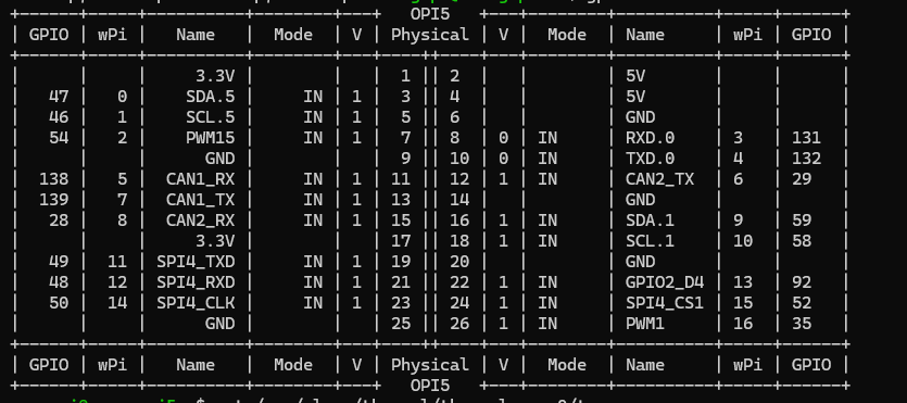
hello, i was trying to set up a 2 pin fan on my orangepi 5b and i connected it to pin 25 and 26 (GND and PWM1). When i first started this task, the output from gpio readall would show me all 26 pins on the board. As i was digging through some forums to try and get the PWM pin to operate as on/off, i came across wiringOP and when i installed it, the output of `gpio readall` changed to only show 8pins. I am unsure of what went wrong and why it only shows 8 pins. I tried removing wiringOP and it still has not made a difference. Thanks

-
Hi, maybe the fragment you applied is not really compatible with your dtb. [ 1.779992] OF: /meson64-reboot: could not get #gpio-cells for /soc/gpu@ffe40000 [ 1.780030] OF: /meson64-reboot: could not get #gpio-cells for /soc/gpu@ffe40000 [ 1.780050] OF: /meson64-reboot: could not get #gpio-cells for /soc/gpu@ffe40000 Can you post here the complete .dts + your modification?
-
Hi I'm using an Orange Pi PC Plus with a LoRa HAT (Semtech SX1278) connected via GPIO. The tool which uses this HAT connects directly to the SX1278 chip on the HAT, no protocoll like SPI is needed. I'm using it for several years on RaspberryPi's without problems. But with the latest ARMBIAN Image for the Orange Pi PC Plus Armbian_23.11.1_Orangepipcplus_bookworm_current_6.1.63.img.xz I have issues in this constellation. The tool can not contact the SX1278 via GPIO, said the tool developer. It seems like I have to activate the GPIO pins before. I've tried to find information about that, but without success. So I hope to find here more information and help. I have to use these hardware PINs (these are the PIN descritions on teh Raspberry Pi): MOSI SPI0_MOSI / GPIO10 (PIN 19) MISO SPI0_MISO / GPIO9 (PIN 21) SCK SPI0_SCLK / GPIO11 (PIN 23) NSS/Enable SPI0_CE0_N / GPIO8 (PIN 24) RST GPIO6 (PIN 31) Thanks in advance.
-
I took a closer look at my R6C https://wiki.friendlyelec.com/wiki/index.php/File:NanoPi_R6C_02.jpg The round thing above the USB-C PD is plastic lid/cover that can be pulled out and that leaves a hole of about 5.85 mm, so 6 mm I guess as I could not measure it well. So you can guess that one can stick a uFL connector through it. I don't see how that can be used for R6C, but at least your question answers mine a bit as well as it seems that hole is good for some (random) GPIO wires as well.
-
@JamesCL Changes: git status On branch main Your branch is up to date with 'origin/main'. Changes not staged for commit: (use "git add <file>..." to update what will be committed) (use "git restore <file>..." to discard changes in working directory) modified: config/boards/radxa-cubie-a5e.conf modified: config/sources/families/sun55iw3.conf Untracked files: (use "git add <file>..." to include in what will be committed) config/boards/orangepi4a.conf patch/kernel/archive/sunxi-dev-6.12/Add-sun55iw3-OrangePi-4A.patch patch/u-boot/sunxi-dev-u-boot-a523/ you should skip the cubie board changes: config/boards/radxa-cubie-a5e.conf config/sources/families/sun55iw3.conf # # SPDX-License-Identifier: GPL-2.0 # # Copyright (c) 2013-2023 Igor Pecovnik, igor@armbian.com # # This file is a part of the Armbian Build Framework # https://github.com/armbian/build/ # enable_extension "sunxi-tools" declare -g ARCH=arm64 declare -g ATFSOURCE='https://github.com/jernejsk/arm-trusted-firmware' declare -g ATF_TARGET_MAP="PLAT=sun55i_a523 DEBUG=1 bl31;;build/sun55i_a523/debug/bl31.bin" declare -g ATFBRANCH="branch:a523" declare -g BOOTSCRIPT='boot-sun50i-next.cmd:boot.cmd' declare -g BOOTDELAY=1 declare -g BOOTSOURCE='https://github.com/jernejsk/u-boot/' declare -g BOOTPATCHDIR="sunxi-dev-${BOOTPATCHDIR:-"u-boot-a523"}" declare -g BOOTBRANCH="${BOOTBRANCH:-"branch:a523"}" declare -g BOOTENV_FILE='sunxi.txt' declare -g UBOOT_TARGET_MAP="${UBOOT_TARGET_MAP:-BINMAN_ALLOW_MISSING=1;;u-boot-sunxi-with-spl.bin}" declare -g OVERLAY_DIR="/boot/dtb/allwinner/overlay" declare -g LINUXFAMILY="sun55iw3" case "${BRANCH}" in dev) declare -g KERNELSOURCE='https://github.com/apritzel/linux' declare -g KERNELBRANCH='branch:a523-v2-WIP' declare -g KERNEL_MAJOR_MINOR="6.12" # Major and minor versions of this kernel. KERNELPATCHDIR="archive/sunxi-dev-${KERNEL_MAJOR_MINOR}" ;; esac family_tweaks() { # execute specific tweaks function if present [[ $(type -t family_tweaks_s) == function ]] && family_tweaks_s cp $SRC/packages/blobs/splash/armbian-u-boot-24.bmp $SDCARD/boot/boot.bmp } write_uboot_platform() { dd if=/dev/zero of=$2 bs=512 count=1023 seek=1 status=noxfer > /dev/null 2>&1 dd if=$1/u-boot-sunxi-with-spl.bin of=$2 bs=512 seek=256 status=noxfer > /dev/null 2>&1 } setup_write_uboot_platform() { local tmp part dev if grep -q "ubootpart" /proc/cmdline; then # mainline with new boot script tmp=$(cat /proc/cmdline) tmp="${tmp##*ubootpart=}" tmp="${tmp%% *}" [[ -n $tmp ]] && part=$(findfs PARTUUID=$tmp 2> /dev/null) [[ -n $part ]] && dev=$(lsblk -n -o PKNAME $part 2> /dev/null) [[ -n $dev ]] && DEVICE="/dev/$dev" else # legacy or old boot script tmp=$(cat /proc/cmdline) tmp="${tmp##*root=}" tmp="${tmp%% *}" [[ -n $tmp ]] && part=$(findfs $tmp 2> /dev/null) [[ -n $part ]] && dev=$(lsblk -n -o PKNAME $part 2> /dev/null) # do not try to write u-boot to USB devices [[ -n $dev && $dev == mmcblk* ]] && DEVICE="/dev/$dev" fi } config/boards/orangepi4a.conf # Allwinner Cortex-A55 octa core SoC BOARD_NAME="Orange Pi 4A" BOARDFAMILY="sun55iw3" BOARD_MAINTAINER="" BOOTCONFIG="orangepi-4a_defconfig" OVERLAY_PREFIX="sun55i-t527" #BOOT_LOGO="desktop" KERNEL_TARGET="dev" patch/kernel/archive/sunxi-dev-6.12/Add-sun55iw3-OrangePi-4A.patch From 0000000000000000000000000000000000000000 Mon Sep 17 00:00:00 2001 From: John Doe <john.doe@somewhere.on.planet> Date: Mon, 24 Feb 2025 21:37:29 -0300 Subject: Add sun55i-t527-orangepi-4a dts file Signed-off-by: John Doe <john.doe@somewhere.on.planet> --- arch/arm64/boot/dts/allwinner/Makefile | 2 + arch/arm64/boot/dts/allwinner/sun55i-t527-orangepi-4a.dts | 375 ++++++++++ 2 files changed, 377 insertions(+) diff --git a/arch/arm64/boot/dts/allwinner/Makefile b/arch/arm64/boot/dts/allwinner/Makefile index 9d5e14695af0..b409e491bf73 100644 --- a/arch/arm64/boot/dts/allwinner/Makefile +++ b/arch/arm64/boot/dts/allwinner/Makefile @@ -53,5 +53,7 @@ dtb-$(CONFIG_ARCH_SUNXI) += sun50i-h700-anbernic-rg35xx-h.dtb dtb-$(CONFIG_ARCH_SUNXI) += sun50i-h700-anbernic-rg35xx-plus.dtb dtb-$(CONFIG_ARCH_SUNXI) += sun50i-h700-anbernic-rg35xx-sp.dtb dtb-$(CONFIG_ARCH_SUNXI) += sun55i-a527-radxa-a5e.dtb dtb-$(CONFIG_ARCH_SUNXI) += sun55i-h728-x96qpro+.dtb dtb-$(CONFIG_ARCH_SUNXI) += sun55i-t527-avaota-a1.dtb +dtb-$(CONFIG_ARCH_SUNXI) += sun55i-t527-orangepi-4a.dtb + diff --git a/arch/arm64/boot/dts/allwinner/sun55i-t527-orangepi-4a.dts b/arch/arm64/boot/dts/allwinner/sun55i-t527-orangepi-4a.dts new file mode 100644 index 000000000000..06046e2555af --- /dev/null +++ b/arch/arm64/boot/dts/allwinner/sun55i-t527-orangepi-4a.dts @@ -0,0 +1,375 @@ +// SPDX-License-Identifier: (GPL-2.0-only OR MIT) +// Copyright (C) 2024 Arm Ltd. + +/dts-v1/; + +#include "sun55i-a523.dtsi" + +#include <dt-bindings/gpio/gpio.h> + +/ { + model = "OrangePi 4A"; + compatible = "xunlong,orangepi-4a", "allwinner,sun55i-t527"; + + aliases { + serial0 = &uart0; + }; + + chosen { + stdout-path = "serial0:115200n8"; + }; + + /* For now, until we have mainline components living in SRAM */ + reserved-memory { + #address-cells = <2>; + #size-cells = <2>; + ranges; + + /* 128 KiB reserved for Trusted Firmware-A (BL31). */ + secmon@48000000 { + reg = <0x0 0x48000000 0x0 0x20000>; + no-map; + }; + + /* 256 KiB reserved for the SCP. */ + secmon@48100000 { + reg = <0x0 0x48100000 0x0 0x40000>; + no-map; + }; + }; + + leds: gpio-leds { + compatible = "gpio-leds"; + pinctrl-names = "default"; + status = "okay"; + + status_led@0 { + gpios = <&pio 3 20 GPIO_ACTIVE_HIGH>; /* PD20 */ + label = "status_led"; + linux,default-trigger = "heartbeat"; + linux,default-trigger-delay-ms = <0>; + }; + }; + + reg_vcc5v: vcc5v { + /* board wide 5V supply from the 12V->5V regulator */ + compatible = "regulator-fixed"; + regulator-name = "vcc-5v"; + regulator-min-microvolt = <5000000>; + regulator-max-microvolt = <5000000>; + regulator-always-on; + }; + + reg_exxt_vbus: exxt-vbus { + compatible = "regulator-fixed"; + regulator-name = "exxxxt-vbus"; + regulator-min-microvolt = <3300000>; + regulator-max-microvolt = <3300000>; + regulator-enable-ramp-delay = <1000>; + gpio = <&r_pio 0 8 GPIO_ACTIVE_HIGH>; + regulator-always-on; + regulator-boot-on; + enable-active-high; + }; + + reg_usb0_vbus: usb0-vbus { + compatible = "regulator-fixed"; + regulator-name = "usb0-vbus"; + regulator-min-microvolt = <5000000>; + regulator-max-microvolt = <5000000>; + regulator-enable-ramp-delay = <1000>; + gpio = <&r_pio 0 4 GPIO_ACTIVE_HIGH>; + regulator-always-on; + regulator-boot-on; + enable-active-high; + }; + + reg_usb1_vbus: usb1-vbus { + compatible = "regulator-fixed"; + regulator-name = "usb1-vbus"; + regulator-min-microvolt = <5000000>; + regulator-max-microvolt = <5000000>; + regulator-enable-ramp-delay = <1000>; + gpio = <&r_pio 0 12 GPIO_ACTIVE_HIGH>; + regulator-always-on; + regulator-boot-on; + enable-active-high; + }; +}; + +&mmc0 { + vmmc-supply = <®_cldo3>; + vqmmc-supply = <®_cldo1>; + cd-gpios = <&pio 5 6 (GPIO_ACTIVE_LOW | GPIO_PULL_DOWN)>; /* PF6 */ + bus-width = <4>; + max-frequency = <20000000>; + status = "okay"; +}; + +&pio { + vcc-pb-supply = <®_cldo3>; + vcc-pc-supply = <®_cldo1>; + vcc-pd-supply = <®_dcdc4>; + vcc-pe-supply = <®_dcdc4>; + vcc-pf-supply = <®_cldo3>; + vcc-pg-supply = <®_bldo1>; + vcc-ph-supply = <®_cldo3>; + vcc-pi-supply = <®_dcdc4>; + vcc-pj-supply = <®_dcdc4>; + vcc-pk-supply = <®_bldo3>; +}; + +&r_i2c0 { + status = "okay"; + + axp717: pmic@35 { + compatible = "x-powers,axp717"; + reg = <0x35>; + interrupt-controller; + #interrupt-cells = <1>; + interrupt-parent = <&nmi_intc>; + interrupts = <0 IRQ_TYPE_LEVEL_LOW>; + + vin1-supply = <®_vcc5v>; + vin2-supply = <®_vcc5v>; + vin3-supply = <®_vcc5v>; + vin4-supply = <®_vcc5v>; + aldoin-supply = <®_vcc5v>; + bldoin-supply = <®_vcc5v>; + cldoin-supply = <®_vcc5v>; + + regulators { + /* Supplies the "little" cluster (1.4 GHz cores) */ + reg_dcdc1: dcdc1 { + regulator-always-on; + regulator-min-microvolt = <900000>; + regulator-max-microvolt = <1160000>; + regulator-name = "vdd-cpu0-3"; + }; + + reg_dcdc2: dcdc2 { + regulator-always-on; + regulator-min-microvolt = <900000>; + regulator-max-microvolt = <1160000>; + regulator-name = "vdd-gpu-sys"; + }; + + reg_dcdc3: dcdc3 { + regulator-always-on; + regulator-min-microvolt = <1160000>; + regulator-max-microvolt = <1160000>; + regulator-name = "vdd-dram"; + }; + + reg_dcdc4: dcdc4 { + regulator-always-on; + regulator-min-microvolt = <3300000>; + regulator-max-microvolt = <3300000>; + regulator-name = "vdd-io"; + }; + + reg_aldo1: aldo1 { + regulator-always-on; + regulator-min-microvolt = <1800000>; + regulator-max-microvolt = <1800000>; + regulator-name = "axp2202-aldo1"; + }; + + reg_aldo2: aldo2 { + regulator-always-on; + regulator-min-microvolt = <1800000>; + regulator-max-microvolt = <1800000>; + regulator-name = "axp2202-aldo2"; + }; + + reg_aldo3: aldo3 { + regulator-always-on; + regulator-min-microvolt = <3300000>; + regulator-max-microvolt = <3300000>; + regulator-name = "vcc-pl-pm"; + }; + + reg_aldo4: aldo4 { + regulator-always-on; + regulator-min-microvolt = <1800000>; + regulator-max-microvolt = <1800000>; + regulator-name = "vcc-pll-dxco-avcc"; + }; + + reg_bldo1: bldo1 { + regulator-always-on; + regulator-min-microvolt = <1800000>; + regulator-max-microvolt = <1800000>; + regulator-name = "vcc-pg-wifi-lvds"; + }; + + reg_bldo2: bldo2 { + regulator-always-on; + regulator-min-microvolt = <1800000>; + regulator-max-microvolt = <1800000>; + regulator-name = "vcc-dram-1v8"; + }; + + reg_bldo3: bldo3 { + regulator-always-on; + regulator-min-microvolt = <1800000>; + regulator-max-microvolt = <1800000>; + regulator-name = "vcc-cvp-pk-vid1v8"; + }; + + reg_bldo4: bldo4 { + regulator-always-on; + regulator-min-microvolt = <1200000>; + regulator-max-microvolt = <1200000>; + regulator-name = "axp2202-bldo4"; + }; + + reg_cldo1: cldo1 { + regulator-always-on; + regulator-min-microvolt = <1800000>; + regulator-max-microvolt = <1800000>; + regulator-name = "vcc-pc"; + }; + + reg_cldo2: cldo2 { + regulator-always-on; + regulator-min-microvolt = <1800000>; + regulator-max-microvolt = <1800000>; + regulator-name = "vcc-efuse"; + }; + + reg_cldo3: cldo3 { + regulator-always-on; + regulator-min-microvolt = <3300000>; + regulator-max-microvolt = <3300000>; + regulator-name = "vcc-mmc-eth-codec"; + }; + + reg_cldo4: cldo4 { + regulator-always-on; + regulator-min-microvolt = <3300000>; + regulator-max-microvolt = <3300000>; + regulator-name = "axp2202-cldo4"; + }; + + reg_cpusldo: cpusldo { + /* supplies the management core */ + regulator-always-on; + regulator-min-microvolt = <900000>; + regulator-max-microvolt = <900000>; + regulator-name = "vdd-cpus"; + }; + }; + }; + + axp323: pmic@36 { + compatible = "x-powers,axp323"; + reg = <0x36>; + #interrupt-cells = <1>; + interrupt-controller; + interrupt-parent = <&nmi_intc>; + interrupts = <0 IRQ_TYPE_LEVEL_LOW>; + status = "okay"; + + vin1-supply = <®_vcc5v>; + vin2-supply = <®_vcc5v>; + vin3-supply = <®_vcc5v>; + + regulators { + /* Supplies the "big" cluster (1.8 GHz cores) */ + reg_dcdc1_323: dcdc1 { + regulator-always-on; + regulator-min-microvolt = <900000>; + regulator-max-microvolt = <1160000>; + regulator-name = "vdd-cpu4-7"; + }; + + reg_dcdc2_323: dcdc2 { + regulator-min-microvolt = <1100000>; + regulator-max-microvolt = <1100000>; + regulator-name = "axp323-dcdc2"; + }; + + reg_dcdc3_323: dcdc3 { + regulator-always-on; + regulator-min-microvolt = <1000000>; + regulator-max-microvolt = <1000000>; + regulator-name = "vdd-npu"; + }; + + reg_aldo1_323: aldo1 { + regulator-name = "axp323-aldo1"; + regulator-min-microvolt = <1800000>; + regulator-max-microvolt = <1800000>; + regulator-always-on; + }; + + reg_dldo1_323: dldo1 { + regulator-name = "axp323-dldo1"; + regulator-min-microvolt = <3300000>; + regulator-max-microvolt = <3300000>; + regulator-always-on; + }; + }; + }; +}; + +&r_pio { +/* + * Specifying the supply would create a circular dependency. + * + * vcc-pl-supply = <®_aldo3>; + */ + vcc-pm-supply = <®_aldo3>; +}; + +&uart0 { + pinctrl-names = "default"; + pinctrl-0 = <&uart0_pb_pins>; + status = "okay"; +}; + +&ehci0 { + drvvbus-supply = <®_usb0_vbus>; + status = "okay"; +}; + +&ohci0 { + drvvbus-supply = <®_usb0_vbus>; + status = "okay"; +}; + +&ehci1 { + drvvbus-supply = <®_usb1_vbus>; + status = "okay"; +}; + +&ohci1 { + drvvbus-supply = <®_usb1_vbus>; + status = "okay"; +}; + +&usbphy { + status = "okay"; +}; + +&gmac1 { + phy-mode = "rgmii"; + pinctrl-names = "default", "sleep"; + pinctrl-0 = <&gmac1_pins_default>; + pinctrl-1 = <&gmac1_pins_sleep>; + aw,soc-phy25m; + tx-delay = <1>; + rx-delay = <3>; + dwmac3v3-supply = <®_cldo3>; + phy3v3-supply = <®_cldo3>; + status = "okay"; +}; + +&gmac1_phy0 { + compatible = "ethernet-phy-ieee802.3-c22"; + reg = <1>; + reset-gpios = <&pio 8 15 GPIO_ACTIVE_LOW>; + reset-assert-us = <15000>; + reset-deassert-us = <100000>; +}; -- Created with Armbian build tools https://github.com/armbian/build patch/u-boot/sunxi-dev-u-boot-a523/Add-u-boot-OrangePi4A-defconfig.patch From 0000000000000000000000000000000000000000 Mon Sep 17 00:00:00 2001 From: John Doe <john.doe@somewhere.on.planet> Date: Mon, 24 Feb 2025 22:04:53 -0300 Subject: Add u-boot orangepi-4a_defconfig Signed-off-by: John Doe <john.doe@somewhere.on.planet> --- arch/arm/dts/sun55i-t527-orangepi-4a.dts | 375 ++++++++++ configs/orangepi-4a_defconfig | 26 + 2 files changed, 401 insertions(+) diff --git a/arch/arm/dts/sun55i-t527-orangepi-4a.dts b/arch/arm/dts/sun55i-t527-orangepi-4a.dts new file mode 100644 index 0000000000..06046e2555 --- /dev/null +++ b/arch/arm/dts/sun55i-t527-orangepi-4a.dts @@ -0,0 +1,375 @@ +// SPDX-License-Identifier: (GPL-2.0-only OR MIT) +// Copyright (C) 2024 Arm Ltd. + +/dts-v1/; + +#include "sun55i-a523.dtsi" + +#include <dt-bindings/gpio/gpio.h> + +/ { + model = "OrangePi 4A"; + compatible = "xunlong,orangepi-4a", "allwinner,sun55i-t527"; + + aliases { + serial0 = &uart0; + }; + + chosen { + stdout-path = "serial0:115200n8"; + }; + + /* For now, until we have mainline components living in SRAM */ + reserved-memory { + #address-cells = <2>; + #size-cells = <2>; + ranges; + + /* 128 KiB reserved for Trusted Firmware-A (BL31). */ + secmon@48000000 { + reg = <0x0 0x48000000 0x0 0x20000>; + no-map; + }; + + /* 256 KiB reserved for the SCP. */ + secmon@48100000 { + reg = <0x0 0x48100000 0x0 0x40000>; + no-map; + }; + }; + + leds: gpio-leds { + compatible = "gpio-leds"; + pinctrl-names = "default"; + status = "okay"; + + status_led@0 { + gpios = <&pio 3 20 GPIO_ACTIVE_HIGH>; /* PD20 */ + label = "status_led"; + linux,default-trigger = "heartbeat"; + linux,default-trigger-delay-ms = <0>; + }; + }; + + reg_vcc5v: vcc5v { + /* board wide 5V supply from the 12V->5V regulator */ + compatible = "regulator-fixed"; + regulator-name = "vcc-5v"; + regulator-min-microvolt = <5000000>; + regulator-max-microvolt = <5000000>; + regulator-always-on; + }; + + reg_exxt_vbus: exxt-vbus { + compatible = "regulator-fixed"; + regulator-name = "exxxxt-vbus"; + regulator-min-microvolt = <3300000>; + regulator-max-microvolt = <3300000>; + regulator-enable-ramp-delay = <1000>; + gpio = <&r_pio 0 8 GPIO_ACTIVE_HIGH>; + regulator-always-on; + regulator-boot-on; + enable-active-high; + }; + + reg_usb0_vbus: usb0-vbus { + compatible = "regulator-fixed"; + regulator-name = "usb0-vbus"; + regulator-min-microvolt = <5000000>; + regulator-max-microvolt = <5000000>; + regulator-enable-ramp-delay = <1000>; + gpio = <&r_pio 0 4 GPIO_ACTIVE_HIGH>; + regulator-always-on; + regulator-boot-on; + enable-active-high; + }; + + reg_usb1_vbus: usb1-vbus { + compatible = "regulator-fixed"; + regulator-name = "usb1-vbus"; + regulator-min-microvolt = <5000000>; + regulator-max-microvolt = <5000000>; + regulator-enable-ramp-delay = <1000>; + gpio = <&r_pio 0 12 GPIO_ACTIVE_HIGH>; + regulator-always-on; + regulator-boot-on; + enable-active-high; + }; +}; + +&mmc0 { + vmmc-supply = <®_cldo3>; + vqmmc-supply = <®_cldo1>; + cd-gpios = <&pio 5 6 (GPIO_ACTIVE_LOW | GPIO_PULL_DOWN)>; /* PF6 */ + bus-width = <4>; + max-frequency = <20000000>; + status = "okay"; +}; + +&pio { + vcc-pb-supply = <®_cldo3>; + vcc-pc-supply = <®_cldo1>; + vcc-pd-supply = <®_dcdc4>; + vcc-pe-supply = <®_dcdc4>; + vcc-pf-supply = <®_cldo3>; + vcc-pg-supply = <®_bldo1>; + vcc-ph-supply = <®_cldo3>; + vcc-pi-supply = <®_dcdc4>; + vcc-pj-supply = <®_dcdc4>; + vcc-pk-supply = <®_bldo3>; +}; + +&r_i2c0 { + status = "okay"; + + axp717: pmic@35 { + compatible = "x-powers,axp717"; + reg = <0x35>; + interrupt-controller; + #interrupt-cells = <1>; + interrupt-parent = <&nmi_intc>; + interrupts = <0 IRQ_TYPE_LEVEL_LOW>; + + vin1-supply = <®_vcc5v>; + vin2-supply = <®_vcc5v>; + vin3-supply = <®_vcc5v>; + vin4-supply = <®_vcc5v>; + aldoin-supply = <®_vcc5v>; + bldoin-supply = <®_vcc5v>; + cldoin-supply = <®_vcc5v>; + + regulators { + /* Supplies the "little" cluster (1.4 GHz cores) */ + reg_dcdc1: dcdc1 { + regulator-always-on; + regulator-min-microvolt = <900000>; + regulator-max-microvolt = <1160000>; + regulator-name = "vdd-cpu0-3"; + }; + + reg_dcdc2: dcdc2 { + regulator-always-on; + regulator-min-microvolt = <900000>; + regulator-max-microvolt = <1160000>; + regulator-name = "vdd-gpu-sys"; + }; + + reg_dcdc3: dcdc3 { + regulator-always-on; + regulator-min-microvolt = <1160000>; + regulator-max-microvolt = <1160000>; + regulator-name = "vdd-dram"; + }; + + reg_dcdc4: dcdc4 { + regulator-always-on; + regulator-min-microvolt = <3300000>; + regulator-max-microvolt = <3300000>; + regulator-name = "vdd-io"; + }; + + reg_aldo1: aldo1 { + regulator-always-on; + regulator-min-microvolt = <1800000>; + regulator-max-microvolt = <1800000>; + regulator-name = "axp2202-aldo1"; + }; + + reg_aldo2: aldo2 { + regulator-always-on; + regulator-min-microvolt = <1800000>; + regulator-max-microvolt = <1800000>; + regulator-name = "axp2202-aldo2"; + }; + + reg_aldo3: aldo3 { + regulator-always-on; + regulator-min-microvolt = <3300000>; + regulator-max-microvolt = <3300000>; + regulator-name = "vcc-pl-pm"; + }; + + reg_aldo4: aldo4 { + regulator-always-on; + regulator-min-microvolt = <1800000>; + regulator-max-microvolt = <1800000>; + regulator-name = "vcc-pll-dxco-avcc"; + }; + + reg_bldo1: bldo1 { + regulator-always-on; + regulator-min-microvolt = <1800000>; + regulator-max-microvolt = <1800000>; + regulator-name = "vcc-pg-wifi-lvds"; + }; + + reg_bldo2: bldo2 { + regulator-always-on; + regulator-min-microvolt = <1800000>; + regulator-max-microvolt = <1800000>; + regulator-name = "vcc-dram-1v8"; + }; + + reg_bldo3: bldo3 { + regulator-always-on; + regulator-min-microvolt = <1800000>; + regulator-max-microvolt = <1800000>; + regulator-name = "vcc-cvp-pk-vid1v8"; + }; + + reg_bldo4: bldo4 { + regulator-always-on; + regulator-min-microvolt = <1200000>; + regulator-max-microvolt = <1200000>; + regulator-name = "axp2202-bldo4"; + }; + + reg_cldo1: cldo1 { + regulator-always-on; + regulator-min-microvolt = <1800000>; + regulator-max-microvolt = <1800000>; + regulator-name = "vcc-pc"; + }; + + reg_cldo2: cldo2 { + regulator-always-on; + regulator-min-microvolt = <1800000>; + regulator-max-microvolt = <1800000>; + regulator-name = "vcc-efuse"; + }; + + reg_cldo3: cldo3 { + regulator-always-on; + regulator-min-microvolt = <3300000>; + regulator-max-microvolt = <3300000>; + regulator-name = "vcc-mmc-eth-codec"; + }; + + reg_cldo4: cldo4 { + regulator-always-on; + regulator-min-microvolt = <3300000>; + regulator-max-microvolt = <3300000>; + regulator-name = "axp2202-cldo4"; + }; + + reg_cpusldo: cpusldo { + /* supplies the management core */ + regulator-always-on; + regulator-min-microvolt = <900000>; + regulator-max-microvolt = <900000>; + regulator-name = "vdd-cpus"; + }; + }; + }; + + axp323: pmic@36 { + compatible = "x-powers,axp323"; + reg = <0x36>; + #interrupt-cells = <1>; + interrupt-controller; + interrupt-parent = <&nmi_intc>; + interrupts = <0 IRQ_TYPE_LEVEL_LOW>; + status = "okay"; + + vin1-supply = <®_vcc5v>; + vin2-supply = <®_vcc5v>; + vin3-supply = <®_vcc5v>; + + regulators { + /* Supplies the "big" cluster (1.8 GHz cores) */ + reg_dcdc1_323: dcdc1 { + regulator-always-on; + regulator-min-microvolt = <900000>; + regulator-max-microvolt = <1160000>; + regulator-name = "vdd-cpu4-7"; + }; + + reg_dcdc2_323: dcdc2 { + regulator-min-microvolt = <1100000>; + regulator-max-microvolt = <1100000>; + regulator-name = "axp323-dcdc2"; + }; + + reg_dcdc3_323: dcdc3 { + regulator-always-on; + regulator-min-microvolt = <1000000>; + regulator-max-microvolt = <1000000>; + regulator-name = "vdd-npu"; + }; + + reg_aldo1_323: aldo1 { + regulator-name = "axp323-aldo1"; + regulator-min-microvolt = <1800000>; + regulator-max-microvolt = <1800000>; + regulator-always-on; + }; + + reg_dldo1_323: dldo1 { + regulator-name = "axp323-dldo1"; + regulator-min-microvolt = <3300000>; + regulator-max-microvolt = <3300000>; + regulator-always-on; + }; + }; + }; +}; + +&r_pio { +/* + * Specifying the supply would create a circular dependency. + * + * vcc-pl-supply = <®_aldo3>; + */ + vcc-pm-supply = <®_aldo3>; +}; + +&uart0 { + pinctrl-names = "default"; + pinctrl-0 = <&uart0_pb_pins>; + status = "okay"; +}; + +&ehci0 { + drvvbus-supply = <®_usb0_vbus>; + status = "okay"; +}; + +&ohci0 { + drvvbus-supply = <®_usb0_vbus>; + status = "okay"; +}; + +&ehci1 { + drvvbus-supply = <®_usb1_vbus>; + status = "okay"; +}; + +&ohci1 { + drvvbus-supply = <®_usb1_vbus>; + status = "okay"; +}; + +&usbphy { + status = "okay"; +}; + +&gmac1 { + phy-mode = "rgmii"; + pinctrl-names = "default", "sleep"; + pinctrl-0 = <&gmac1_pins_default>; + pinctrl-1 = <&gmac1_pins_sleep>; + aw,soc-phy25m; + tx-delay = <1>; + rx-delay = <3>; + dwmac3v3-supply = <®_cldo3>; + phy3v3-supply = <®_cldo3>; + status = "okay"; +}; + +&gmac1_phy0 { + compatible = "ethernet-phy-ieee802.3-c22"; + reg = <1>; + reset-gpios = <&pio 8 15 GPIO_ACTIVE_LOW>; + reset-assert-us = <15000>; + reset-deassert-us = <100000>; +}; diff --git a/configs/orangepi-4a_defconfig b/configs/orangepi-4a_defconfig new file mode 100644 index 0000000000..5a9422535c --- /dev/null +++ b/configs/orangepi-4a_defconfig @@ -0,0 +1,26 @@ +CONFIG_ARM=y +CONFIG_ARCH_SUNXI=y +CONFIG_SUNXI_ARMV8_32BIT_BUILD=y +CONFIG_DEFAULT_DEVICE_TREE="sun55i-a527-orangepi-4a" +CONFIG_SPL=y +CONFIG_DRAM_SUNXI_DX_ODT=0x07070707 +CONFIG_DRAM_SUNXI_DX_DRI=0x0d0d0d0d +CONFIG_DRAM_SUNXI_CA_DRI=0x0e0e +CONFIG_DRAM_SUNXI_ODT_EN=0x84848484 +CONFIG_DRAM_SUNXI_TPR0=0x80808080 +CONFIG_DRAM_SUNXI_TPR1=0x06060606 +CONFIG_DRAM_SUNXI_TPR6=0x38000000 +CONFIG_DRAM_SUNXI_TPR10=0x802f3333 +CONFIG_DRAM_SUNXI_TPR11=0xc6c4c2c0 +CONFIG_DRAM_SUNXI_TPR12=0x3a373233 +CONFIG_MACH_SUN55I_A523=y +CONFIG_R_I2C_ENABLE=y +# CONFIG_SYS_MALLOC_CLEAR_ON_INIT is not set +CONFIG_SPL_I2C=y +CONFIG_SPL_SYS_I2C_LEGACY=y +CONFIG_SYS_I2C_MVTWSI=y +CONFIG_SYS_I2C_SLAVE=0x7f +CONFIG_SYS_I2C_SPEED=400000 +CONFIG_AXP717_POWER=y +CONFIG_AXP_DCDC2_VOLT=920 +CONFIG_AXP_DCDC3_VOLT=1100 -- Created with Armbian build tools https://github.com/armbian/build patch/u-boot/sunxi-dev-u-boot-a523/Fix-uboot-sun55iw3-orangepi4a.patch From 0000000000000000000000000000000000000000 Mon Sep 17 00:00:00 2001 From: John Doe <john.doe@somewhere.on.planet> Date: Mon, 24 Feb 2025 23:29:02 -0300 Subject: Fix u-boot sun55iw3-orangepi-4a Signed-off-by: John Doe <john.doe@somewhere.on.planet> --- arch/arm/dts/sun55i-t527-orangepi-4a.dts | 21 ---------- configs/orangepi-4a_defconfig | 2 +- 2 files changed, 1 insertion(+), 22 deletions(-) diff --git a/arch/arm/dts/sun55i-t527-orangepi-4a.dts b/arch/arm/dts/sun55i-t527-orangepi-4a.dts index 06046e2555..d6e291c3b1 100644 --- a/arch/arm/dts/sun55i-t527-orangepi-4a.dts +++ b/arch/arm/dts/sun55i-t527-orangepi-4a.dts @@ -350,26 +350,5 @@ }; &usbphy { status = "okay"; }; - -&gmac1 { - phy-mode = "rgmii"; - pinctrl-names = "default", "sleep"; - pinctrl-0 = <&gmac1_pins_default>; - pinctrl-1 = <&gmac1_pins_sleep>; - aw,soc-phy25m; - tx-delay = <1>; - rx-delay = <3>; - dwmac3v3-supply = <®_cldo3>; - phy3v3-supply = <®_cldo3>; - status = "okay"; -}; - -&gmac1_phy0 { - compatible = "ethernet-phy-ieee802.3-c22"; - reg = <1>; - reset-gpios = <&pio 8 15 GPIO_ACTIVE_LOW>; - reset-assert-us = <15000>; - reset-deassert-us = <100000>; -}; diff --git a/configs/orangepi-4a_defconfig b/configs/orangepi-4a_defconfig index 5a9422535c..10901edfc7 100644 --- a/configs/orangepi-4a_defconfig +++ b/configs/orangepi-4a_defconfig @@ -1,9 +1,9 @@ CONFIG_ARM=y CONFIG_ARCH_SUNXI=y CONFIG_SUNXI_ARMV8_32BIT_BUILD=y -CONFIG_DEFAULT_DEVICE_TREE="sun55i-a527-orangepi-4a" +CONFIG_DEFAULT_DEVICE_TREE="sun55i-t527-orangepi-4a" CONFIG_SPL=y CONFIG_DRAM_SUNXI_DX_ODT=0x07070707 CONFIG_DRAM_SUNXI_DX_DRI=0x0d0d0d0d CONFIG_DRAM_SUNXI_CA_DRI=0x0e0e CONFIG_DRAM_SUNXI_ODT_EN=0x84848484 -- Created with Armbian build tools https://github.com/armbian/build Those were the changes I made, I don't have the board to be able to test and try to repair the compilation, if someone has the board and can make the missing changes maybe this will help. You need to clone the following repository to apply the above changes: https://github.com/juanesf/build.git
-
Yesterday, I tried to use the digital IO in my opi zero3, with the Python GPIO package from https://opi-gpio.readthedocs.io/en/latest/ by Richard Hull It depends on having sysfs files in /sys/class/gpio/ My original opi zero has these files and it works, but my opi zero3 doesn’t have these files I learned that /sys/class/gpio is created if the linux kernel is configured with a specific option ON, as suggested in the documentation: https://github.com/rm-hull/OPi.GPIO https://linux-sunxi.org/GPIO Also, a developer has made a change on the opi.GPIO project to support opi zero3 https://github.com/rm-hull/OPi.GPIO/issues/79 I will have time to try this tomorrow... but I want to ask: is anyone using GPIO in its most basic way? As reference: I saw this older thread about zero3's GPIO... https://forum.armbian.com/topic/31493-how-to-enable-i2c3-on-orange-pi-zero-3/ It is using leebobby's "armbian" image, with raspi-config, and wiringpi Using my original opi-zero, I never needed to use armbian-config to enable basic gpio and the python opi.gpio just worked as documented Note: the opi.gpio only claims to support basic gpio, not i2c. Update: these are interesting potential solutions and discussions (but they are all from before there was armbian for opiz3) https://www.reddit.com/r/OrangePI/comments/16vfa4g/orange_pi_zero_3_gpio_python_library/ https://github.com/eutim/OPI.GPIO https://www.reddit.com/r/OrangePI/comments/16ioyri/gpio_python_library_for_orange_pi_zero_3/ https://www.reddit.com/r/OrangePI/comments/18iveo3/how_to_control_gpio_pins_in_android_orange_pi/
-
I see from:https://wiki.friendlyelec.com/wiki/index.php/NanoPi_M6 M.2 Connectors one M.2 M-Key connector with PCIe 2.1 x1 for SSDs one M.2 E-key connector with PCIe 2.1 x1 and USB2.0 Host for Wi-Fi&BT So any E-Key WiFi 2230 sized card should work if it has the correct and needed signals. Of course there must be the correct kernel driver modules. I have a NanoPi-R6C, sofar I only unscrewed the bottom plate to put a 2280 M-key NVMe SSD in it. But I might drill a hole somewhere for a GPIO 1-wire or so later this year.
-
@MaxT okay, the Orange pi 5 has 26 GPIO instead of 40, that would be the pin out: http://www.orangepi.org/orangepiwiki/index.php/26_Pin_Interface_Pin_Description I see pin 19, 21, and 23 are related to SPI, which of those would you ground? MOSI (input?) MISO (output) or the clock? SPI4_MOSI_M0 pin 19 SPI4_MISO_M0 pin 21 SPI4_CLK_M0 pin 23 SPI4_CS1_M0 pin 24 Thank you man! its fun to try all this stuff
-
TX95 Max - Allwinner H618 Quadcore Cortex - A53
Mark Waples replied to Mark Waples's topic in Allwinner CPU Boxes
Hi, Nick that's great information - thank you! It all checks out. The only command that worked was: echo alarm > /sys/class/leds/openvfd/led_on This turned on the wifi-eth and usb leds all together and not blinking. I went to see what was in the device tree but the new armbian-configNG does not have the DTS editor available as in the old config tool. I don't know if there is a way of reverting back to the old tool (I froze Kernal Updates in the old tool) so it's very useful and I don't know why it has installed the new one as it does not have many features like the old config tool. I hate when things are forced upon you. So am I going to be forced to install DTC to decompile the Device Tree (DTB)? ------------------------------------------------------------------------ CONVERT dtb to dts ------------------------------------------------------------------------ dtc -I dtb -O dts /boot/dtb/allwinner/sun50i-h618-transpeed-8k618-t.dtb -o /boot/dtb/allwinner/sun50i-h618-transpeed-8k618-t.dts ------------------------------------------------------------------------ EDIT dts ------------------------------------------------------------------------ nano /boot/dtb/allwinner/sun50i-h618-transpeed-8k618-t.dts ------------------------------------------------------------------------ CONVERT (BACK) dts to dtb ------------------------------------------------------------------------ dtc -I dts -O dtb /boot/dtb/allwinner/sun50i-h618-transpeed-8k618-t.dts -o /boot/dtb/allwinner/sun50i-h618-transpeed-8k618-t.dtb I assume my tree is called sun50i-h618-transpeed-8k618-t.dtb and here is the contents of that tree /dts-v1/; / { interrupt-parent = <0x01>; #address-cells = <0x02>; #size-cells = <0x02>; model = "Transpeed 8K618-T"; compatible = "transpeed,8k618-t\0allwinner,sun50i-h618"; cpus { #address-cells = <0x01>; #size-cells = <0x00>; cpu@0 { compatible = "arm,cortex-a53"; device_type = "cpu"; reg = <0x00>; enable-method = "psci"; clocks = <0x02 0x15>; #cooling-cells = <0x02>; operating-points-v2 = <0x03>; cpu-supply = <0x04>; status = "okay"; phandle = <0x06>; }; cpu@1 { compatible = "arm,cortex-a53"; device_type = "cpu"; reg = <0x01>; enable-method = "psci"; clocks = <0x02 0x15>; #cooling-cells = <0x02>; operating-points-v2 = <0x03>; phandle = <0x07>; }; cpu@2 { compatible = "arm,cortex-a53"; device_type = "cpu"; reg = <0x02>; enable-method = "psci"; clocks = <0x02 0x15>; #cooling-cells = <0x02>; operating-points-v2 = <0x03>; phandle = <0x08>; }; cpu@3 { compatible = "arm,cortex-a53"; device_type = "cpu"; reg = <0x03>; enable-method = "psci"; clocks = <0x02 0x15>; #cooling-cells = <0x02>; operating-points-v2 = <0x03>; phandle = <0x09>; }; }; display-engine { compatible = "allwinner,sun50i-h6-display-engine"; allwinner,pipelines = <0x05>; status = "okay"; phandle = <0x3b>; }; reserved-memory { #address-cells = <0x02>; #size-cells = <0x02>; ranges; secmon@40000000 { reg = <0x00 0x40000000 0x00 0x80000>; no-map; }; }; osc24M-clk { #clock-cells = <0x00>; compatible = "fixed-clock"; clock-frequency = <0x16e3600>; clock-output-names = "osc24M"; phandle = <0x0f>; }; pmu { compatible = "arm,cortex-a53-pmu"; interrupts = <0x00 0x8c 0x04 0x00 0x8d 0x04 0x00 0x8e 0x04 0x00 0x8f 0x04>; interrupt-affinity = <0x06 0x07 0x08 0x09>; }; psci { compatible = "arm,psci-0.2"; method = "smc"; }; timer { compatible = "arm,armv8-timer"; arm,no-tick-in-suspend; interrupts = <0x01 0x0d 0xf04 0x01 0x0e 0xf04 0x01 0x0b 0xf04 0x01 0x0a 0xf04>; }; soc { compatible = "simple-bus"; #address-cells = <0x01>; #size-cells = <0x01>; ranges = <0x00 0x00 0x00 0x40000000>; bus@1000000 { compatible = "allwinner,sun50i-h616-de33\0allwinner,sun50i-a64-de2"; reg = <0x1000000 0x400000>; allwinner,sram = <0x0a 0x01>; #address-cells = <0x01>; #size-cells = <0x01>; ranges = <0x00 0x1000000 0x400000>; clock@8000 { compatible = "allwinner,sun50i-h616-de33-clk"; reg = <0x8000 0x100>; clocks = <0x02 0x1d 0x02 0x1e>; clock-names = "mod\0bus"; resets = <0x02 0x01>; #clock-cells = <0x01>; #reset-cells = <0x01>; phandle = <0x0b>; }; mixer@100000 { compatible = "allwinner,sun50i-h616-de33-mixer-0"; reg = <0x100000 0x100000 0x8100 0x40 0x280000 0x20000>; clocks = <0x0b 0x00 0x0b 0x06>; clock-names = "bus\0mod"; resets = <0x0b 0x00>; phandle = <0x05>; ports { #address-cells = <0x01>; #size-cells = <0x00>; port@1 { reg = <0x01>; phandle = <0x3c>; endpoint { remote-endpoint = <0x0c>; phandle = <0x2c>; }; }; }; }; }; gpu@1800000 { compatible = "allwinner,sun50i-h616-mali\0arm,mali-bifrost"; reg = <0x1800000 0x40000>; interrupts = <0x00 0x5f 0x04 0x00 0x60 0x04 0x00 0x61 0x04>; interrupt-names = "job\0mmu\0gpu"; clocks = <0x02 0x23 0x02 0x24>; clock-names = "core\0bus"; resets = <0x02 0x03>; status = "okay"; mali-supply = <0x0d>; phandle = <0x3d>; }; deinterlace@1420000 { compatible = "allwinner,sun50i-h6-deinterlace"; reg = <0x1420000 0x40000>; clocks = <0x02 0x20 0x02 0x1f 0x02 0x33>; clock-names = "bus\0mod\0ram"; resets = <0x02 0x02>; interrupts = <0x00 0x59 0x04>; phandle = <0x3e>; }; video-codec@1c0e000 { compatible = "allwinner,sun50i-h616-video-engine"; reg = <0x1c0e000 0x2000>; clocks = <0x02 0x29 0x02 0x28 0x02 0x33>; clock-names = "ahb\0mod\0ram"; resets = <0x02 0x05>; interrupts = <0x00 0x5d 0x04>; allwinner,sram = <0x0e 0x01>; }; syscon@3000000 { compatible = "allwinner,sun50i-h616-system-control"; reg = <0x3000000 0x1000>; #address-cells = <0x01>; #size-cells = <0x01>; ranges; phandle = <0x23>; sram@100000 { compatible = "mmio-sram"; reg = <0x100000 0x18000>; #address-cells = <0x01>; #size-cells = <0x01>; ranges = <0x00 0x100000 0x18000>; phandle = <0x3f>; scpi-sram@17c00 { compatible = "arm,scp-shmem"; reg = <0x17c00 0x200>; phandle = <0x40>; }; }; sram@28000 { compatible = "mmio-sram"; reg = <0x28000 0x30000>; #address-cells = <0x01>; #size-cells = <0x01>; ranges = <0x00 0x28000 0x30000>; phandle = <0x41>; sram-section@0 { compatible = "allwinner,sun50i-h616-sram-c\0allwinner,sun50i-a64-sram-c"; reg = <0x00 0x1e000>; phandle = <0x0a>; }; }; sram@1a00000 { compatible = "mmio-sram"; reg = <0x1a00000 0x200000>; #address-cells = <0x01>; #size-cells = <0x01>; ranges = <0x00 0x1a00000 0x200000>; phandle = <0x42>; sram-section@0 { compatible = "allwinner,sun50i-h616-sram-c1"; reg = <0x00 0x200000>; phandle = <0x0e>; }; }; }; clock@3001000 { compatible = "allwinner,sun50i-h616-ccu"; reg = <0x3001000 0x1000>; clocks = <0x0f 0x10 0x00 0x10 0x02>; clock-names = "hosc\0losc\0iosc"; #clock-cells = <0x01>; #reset-cells = <0x01>; phandle = <0x02>; }; dma-controller@3002000 { compatible = "allwinner,sun50i-h616-dma\0allwinner,sun50i-a100-dma"; reg = <0x3002000 0x1000>; interrupts = <0x00 0x2a 0x04>; clocks = <0x02 0x2a 0x02 0x32>; clock-names = "bus\0mbus"; dma-channels = <0x10>; dma-requests = <0x31>; resets = <0x02 0x06>; #dma-cells = <0x01>; phandle = <0x18>; }; efuse@3006000 { compatible = "allwinner,sun50i-h616-sid\0allwinner,sun50i-a64-sid"; reg = <0x3006000 0x1000>; #address-cells = <0x01>; #size-cells = <0x01>; phandle = <0x43>; thermal-sensor-calibration@14 { reg = <0x14 0x08>; phandle = <0x25>; }; cpu-speed-grade@0 { reg = <0x00 0x02>; phandle = <0x38>; }; }; watchdog@30090a0 { compatible = "allwinner,sun50i-h616-wdt\0allwinner,sun6i-a31-wdt"; reg = <0x30090a0 0x20>; interrupts = <0x00 0x32 0x04>; clocks = <0x0f>; phandle = <0x44>; }; pinctrl@300b000 { compatible = "allwinner,sun50i-h616-pinctrl"; reg = <0x300b000 0x400>; interrupts = <0x00 0x33 0x04 0x00 0x34 0x04 0x00 0x35 0x04 0x00 0x2b 0x04 0x00 0x36 0x04 0x00 0x37 0x04 0x00 0x38 0x04 0x00 0x39 0x04>; clocks = <0x02 0x1a 0x0f 0x10 0x00>; clock-names = "apb\0hosc\0losc"; gpio-controller; #gpio-cells = <0x03>; interrupt-controller; #interrupt-cells = <0x03>; vcc-pc-supply = <0x11>; vcc-pg-supply = <0x12>; vcc-ph-supply = <0x12>; vcc-pi-supply = <0x12>; phandle = <0x14>; rgmii-pins { pins = "PI0\0PI1\0PI2\0PI3\0PI4\0PI5\0PI7\0PI8\0PI9\0PI10\0PI11\0PI12\0PI13\0PI14\0PI15\0PI16"; function = "emac0"; drive-strength = <0x28>; phandle = <0x45>; }; i2c0-pins { pins = "PI5\0PI6"; function = "i2c0"; phandle = <0x20>; }; i2c2-ph-pins { pins = "PH2\0PH3"; function = "i2c2"; phandle = <0x46>; }; i2c3-ph-pins { pins = "PH4\0PH5"; function = "i2c3"; phandle = <0x47>; }; i2c4-ph-pins { pins = "PH6\0PH7"; function = "i2c4"; phandle = <0x48>; }; i2c3-pg-pins { pins = "PG17\0PG18"; function = "i2c3"; phandle = <0x49>; }; i2c4-pg-pins { pins = "PG15\0PG16"; function = "i2c4"; phandle = <0x4a>; }; ir-rx-pin { pins = "PH10"; function = "ir_rx"; phandle = <0x34>; }; mmc0-pins { pins = "PF0\0PF1\0PF2\0PF3\0PF4\0PF5"; function = "mmc0"; drive-strength = <0x1e>; bias-pull-up; phandle = <0x13>; }; mmc1-pins { pins = "PG0\0PG1\0PG2\0PG3\0PG4\0PG5"; function = "mmc1"; drive-strength = <0x1e>; bias-pull-up; phandle = <0x15>; }; mmc2-pins { pins = "PC0\0PC1\0PC5\0PC6\0PC8\0PC9\0PC10\0PC11\0PC13\0PC14\0PC15\0PC16"; function = "mmc2"; drive-strength = <0x1e>; bias-pull-up; phandle = <0x17>; }; rmii-pins { pins = "PA0\0PA1\0PA2\0PA3\0PA4\0PA5\0PA6\0PA7\0PA8\0PA9"; function = "emac1"; drive-strength = <0x28>; phandle = <0x26>; }; spi0-pins { pins = "PC0\0PC2\0PC4"; function = "spi0"; phandle = <0x21>; }; spi0-cs0-pin { pins = "PC3"; function = "spi0"; phandle = <0x4b>; }; spi1-pins { pins = "PH6\0PH7\0PH8"; function = "spi1"; phandle = <0x22>; }; spi1-cs0-pin { pins = "PH5"; function = "spi1"; phandle = <0x4c>; }; spi1-cs1-pin { pins = "PH9"; function = "spi1"; phandle = <0x4d>; }; spdif-tx-pin { pins = "PH4"; function = "spdif"; phandle = <0x24>; }; uart0-ph-pins { pins = "PH0\0PH1"; function = "uart0"; phandle = <0x1d>; }; uart2-pins { pins = "PH5\0PH6"; function = "uart2"; phandle = <0x4e>; }; uart2-rts-cts-pins { pins = "PH7\0PH8"; function = "uart2"; phandle = <0x4f>; }; uart5-pins { pins = "PH2\0PH3"; function = "uart5"; phandle = <0x50>; }; uart1-pins { pins = "PG6\0PG7"; function = "uart1"; phandle = <0x1e>; }; uart1-rts-cts-pins { pins = "PG8\0PG9"; function = "uart1"; phandle = <0x1f>; }; x32clk-fanout-pin { pins = "PG10"; function = "clock"; phandle = <0x3a>; }; }; interrupt-controller@3021000 { compatible = "arm,gic-400"; reg = <0x3021000 0x1000 0x3022000 0x2000 0x3024000 0x2000 0x3026000 0x2000>; interrupts = <0x01 0x09 0xf04>; interrupt-controller; #interrupt-cells = <0x03>; phandle = <0x01>; }; iommu@30f0000 { compatible = "allwinner,sun50i-h616-iommu\0allwinner,sun50i-h6-iommu"; reg = <0x30f0000 0x10000>; interrupts = <0x00 0x3d 0x04>; clocks = <0x02 0x30>; resets = <0x02 0x0b>; #iommu-cells = <0x01>; status = "okay"; phandle = <0x51>; }; mmc@4020000 { compatible = "allwinner,sun50i-h616-mmc\0allwinner,sun50i-a100-mmc"; reg = <0x4020000 0x1000>; clocks = <0x02 0x3f 0x02 0x3c>; clock-names = "ahb\0mmc"; resets = <0x02 0x0e>; reset-names = "ahb"; interrupts = <0x00 0x23 0x04>; pinctrl-names = "default"; pinctrl-0 = <0x13>; status = "okay"; max-frequency = <0x8f0d180>; cap-sd-highspeed; cap-mmc-highspeed; mmc-ddr-3_3v; cap-sdio-irq; #address-cells = <0x01>; #size-cells = <0x00>; vmmc-supply = <0x12>; cd-gpios = <0x14 0x08 0x10 0x01>; bus-width = <0x04>; phandle = <0x52>; }; mmc@4021000 { compatible = "allwinner,sun50i-h616-mmc\0allwinner,sun50i-a100-mmc"; reg = <0x4021000 0x1000>; clocks = <0x02 0x40 0x02 0x3d>; clock-names = "ahb\0mmc"; resets = <0x02 0x0f>; reset-names = "ahb"; interrupts = <0x00 0x24 0x04>; pinctrl-names = "default"; pinctrl-0 = <0x15>; status = "okay"; max-frequency = <0x8f0d180>; cap-sd-highspeed; cap-mmc-highspeed; mmc-ddr-3_3v; cap-sdio-irq; #address-cells = <0x01>; #size-cells = <0x00>; vmmc-supply = <0x12>; vqmmc-supply = <0x11>; mmc-pwrseq = <0x16>; bus-width = <0x04>; non-removable; phandle = <0x53>; wifi@1 { reg = <0x01>; phandle = <0x54>; }; }; mmc@4022000 { compatible = "allwinner,sun50i-h616-emmc\0allwinner,sun50i-a100-emmc"; reg = <0x4022000 0x1000>; clocks = <0x02 0x41 0x02 0x3e>; clock-names = "ahb\0mmc"; resets = <0x02 0x10>; reset-names = "ahb"; interrupts = <0x00 0x25 0x04>; pinctrl-names = "default"; pinctrl-0 = <0x17>; status = "okay"; max-frequency = <0x8f0d180>; cap-sd-highspeed; cap-mmc-highspeed; mmc-ddr-3_3v; cap-sdio-irq; #address-cells = <0x01>; #size-cells = <0x00>; vmmc-supply = <0x12>; vqmmc-supply = <0x11>; bus-width = <0x08>; non-removable; cap-mmc-hw-reset; mmc-ddr-1_8v; mmc-hs200-1_8v; phandle = <0x55>; }; codec@05096000 { #sound-dai-cells = <0x00>; compatible = "allwinner,sun50i-h616-codec"; reg = <0x5096000 0x31c>; interrupts = <0x00 0x3a 0x04>; clocks = <0x02 0x5d 0x02 0x5b 0x02 0x5c>; clock-names = "apb\0audio-codec-1x\0audio-codec-4x"; resets = <0x02 0x24>; dmas = <0x18 0x06>; dma-names = "tx"; status = "okay"; allwinner,audio-routing = "Line Out\0LINEOUT"; phandle = <0x56>; }; ahub_dam_plat@5097000 { #sound-dai-cells = <0x00>; compatible = "allwinner,sunxi-snd-plat-ahub_dam"; reg = <0x5097000 0x1000>; resets = <0x02 0x25>; clocks = <0x02 0x5b 0x02 0x5c 0x02 0x5e 0x02 0x5f>; clock-names = "clk_pll_audio\0clk_pll_audio_4x\0clk_audio_hub\0clk_bus_audio_hub"; status = "okay"; phandle = <0x19>; }; ahub_dam_mach { compatible = "allwinner,sunxi-snd-mach"; soundcard-mach,name = "ahubdam"; status = "okay"; phandle = <0x57>; soundcard-mach,cpu { sound-dai = <0x19>; }; soundcard-mach,codec { }; }; ahub1_plat { #sound-dai-cells = <0x00>; compatible = "allwinner,sunxi-snd-plat-ahub"; apb_num = <0x01>; dmas = <0x18 0x04 0x18 0x04>; dma-names = "tx\0rx"; playback_cma = <0x80>; capture_cma = <0x80>; tx_fifo_size = <0x80>; rx_fifo_size = <0x80>; tdm_num = <0x01>; tx_pin = <0x00>; rx_pin = <0x00>; status = "okay"; phandle = <0x1b>; }; ahub1_mach { compatible = "allwinner,sunxi-snd-mach"; soundcard-mach,name = "HDMI"; soundcard-mach,format = "i2s"; soundcard-mach,frame-master = <0x1a>; soundcard-mach,bitclock-master = <0x1a>; soundcard-mach,slot-num = <0x02>; soundcard-mach,slot-width = <0x20>; status = "okay"; phandle = <0x58>; soundcard-mach,cpu { sound-dai = <0x1b>; soundcard-mach,pll-fs = <0x04>; soundcard-mach,mclk-fs = <0x00>; phandle = <0x1a>; }; soundcard-mach,codec { sound-dai = <0x1c>; phandle = <0x59>; }; }; serial@5000000 { compatible = "snps,dw-apb-uart"; reg = <0x5000000 0x400>; interrupts = <0x00 0x00 0x04>; reg-shift = <0x02>; reg-io-width = <0x04>; clocks = <0x02 0x42>; dmas = <0x18 0x0e 0x18 0x0e>; dma-names = "tx\0rx"; resets = <0x02 0x11>; status = "okay"; pinctrl-names = "default"; pinctrl-0 = <0x1d>; phandle = <0x5a>; }; serial@5000400 { compatible = "snps,dw-apb-uart"; reg = <0x5000400 0x400>; interrupts = <0x00 0x01 0x04>; reg-shift = <0x02>; reg-io-width = <0x04>; clocks = <0x02 0x43>; dmas = <0x18 0x0f 0x18 0x0f>; dma-names = "tx\0rx"; resets = <0x02 0x12>; status = "okay"; pinctrl-names = "default"; pinctrl-0 = <0x1e 0x1f>; uart-has-rtscts; phandle = <0x5b>; bluetooth { compatible = "brcm,bcm43438-bt"; shutdown-gpios = <0x14 0x06 0x13 0x00>; clocks = <0x10 0x01>; host-wakeup-gpios = <0x14 0x06 0x10 0x00>; clock-names = "lpo"; vddio-supply = <0x12>; device-wakeup-gpios = <0x14 0x06 0x11 0x00>; vbat-supply = <0x12>; }; }; serial@5000800 { compatible = "snps,dw-apb-uart"; reg = <0x5000800 0x400>; interrupts = <0x00 0x02 0x04>; reg-shift = <0x02>; reg-io-width = <0x04>; clocks = <0x02 0x44>; dmas = <0x18 0x10 0x18 0x10>; dma-names = "tx\0rx"; resets = <0x02 0x13>; status = "disabled"; phandle = <0x5c>; }; serial@5000c00 { compatible = "snps,dw-apb-uart"; reg = <0x5000c00 0x400>; interrupts = <0x00 0x03 0x04>; reg-shift = <0x02>; reg-io-width = <0x04>; clocks = <0x02 0x45>; dmas = <0x18 0x11 0x18 0x11>; dma-names = "tx\0rx"; resets = <0x02 0x14>; status = "disabled"; phandle = <0x5d>; }; serial@5001000 { compatible = "snps,dw-apb-uart"; reg = <0x5001000 0x400>; interrupts = <0x00 0x04 0x04>; reg-shift = <0x02>; reg-io-width = <0x04>; clocks = <0x02 0x46>; dmas = <0x18 0x12 0x18 0x12>; dma-names = "tx\0rx"; resets = <0x02 0x15>; status = "disabled"; phandle = <0x5e>; }; serial@5001400 { compatible = "snps,dw-apb-uart"; reg = <0x5001400 0x400>; interrupts = <0x00 0x05 0x04>; reg-shift = <0x02>; reg-io-width = <0x04>; clocks = <0x02 0x47>; dmas = <0x18 0x13 0x18 0x13>; dma-names = "tx\0rx"; resets = <0x02 0x16>; status = "disabled"; phandle = <0x5f>; }; i2c@5002000 { compatible = "allwinner,sun50i-h616-i2c\0allwinner,sun8i-v536-i2c\0allwinner,sun6i-a31-i2c"; reg = <0x5002000 0x400>; interrupts = <0x00 0x06 0x04>; clocks = <0x02 0x48>; dmas = <0x18 0x2b 0x18 0x2b>; dma-names = "rx\0tx"; resets = <0x02 0x17>; pinctrl-names = "default"; pinctrl-0 = <0x20>; status = "disabled"; #address-cells = <0x01>; #size-cells = <0x00>; phandle = <0x60>; }; i2c@5002400 { compatible = "allwinner,sun50i-h616-i2c\0allwinner,sun8i-v536-i2c\0allwinner,sun6i-a31-i2c"; reg = <0x5002400 0x400>; interrupts = <0x00 0x07 0x04>; clocks = <0x02 0x49>; dmas = <0x18 0x2c 0x18 0x2c>; dma-names = "rx\0tx"; resets = <0x02 0x18>; status = "disabled"; #address-cells = <0x01>; #size-cells = <0x00>; phandle = <0x61>; }; i2c@5002800 { compatible = "allwinner,sun50i-h616-i2c\0allwinner,sun8i-v536-i2c\0allwinner,sun6i-a31-i2c"; reg = <0x5002800 0x400>; interrupts = <0x00 0x08 0x04>; clocks = <0x02 0x4a>; dmas = <0x18 0x2d 0x18 0x2d>; dma-names = "rx\0tx"; resets = <0x02 0x19>; status = "disabled"; #address-cells = <0x01>; #size-cells = <0x00>; phandle = <0x62>; }; i2c@5002c00 { compatible = "allwinner,sun50i-h616-i2c\0allwinner,sun8i-v536-i2c\0allwinner,sun6i-a31-i2c"; reg = <0x5002c00 0x400>; interrupts = <0x00 0x09 0x04>; clocks = <0x02 0x4b>; dmas = <0x18 0x2e 0x18 0x2e>; dma-names = "rx\0tx"; resets = <0x02 0x1a>; status = "okay"; #address-cells = <0x01>; #size-cells = <0x00>; phandle = <0x63>; }; i2c@5003000 { compatible = "allwinner,sun50i-h616-i2c\0allwinner,sun8i-v536-i2c\0allwinner,sun6i-a31-i2c"; reg = <0x5003000 0x400>; interrupts = <0x00 0x0a 0x04>; clocks = <0x02 0x4c>; dmas = <0x18 0x2f 0x18 0x2f>; dma-names = "rx\0tx"; resets = <0x02 0x1b>; status = "disabled"; #address-cells = <0x01>; #size-cells = <0x00>; phandle = <0x64>; }; spi@5010000 { compatible = "allwinner,sun50i-h616-spi\0allwinner,sun8i-h3-spi"; reg = <0x5010000 0x1000>; interrupts = <0x00 0x0c 0x04>; clocks = <0x02 0x4f 0x02 0x4d>; clock-names = "ahb\0mod"; dmas = <0x18 0x16 0x18 0x16>; dma-names = "rx\0tx"; resets = <0x02 0x1c>; pinctrl-names = "default"; pinctrl-0 = <0x21>; status = "disabled"; #address-cells = <0x01>; #size-cells = <0x00>; phandle = <0x65>; }; spi@5011000 { compatible = "allwinner,sun50i-h616-spi\0allwinner,sun8i-h3-spi"; reg = <0x5011000 0x1000>; interrupts = <0x00 0x0d 0x04>; clocks = <0x02 0x50 0x02 0x4e>; clock-names = "ahb\0mod"; dmas = <0x18 0x17 0x18 0x17>; dma-names = "rx\0tx"; resets = <0x02 0x1d>; pinctrl-names = "default"; pinctrl-0 = <0x22>; status = "disabled"; #address-cells = <0x01>; #size-cells = <0x00>; phandle = <0x66>; }; ethernet@5020000 { compatible = "allwinner,sun50i-h616-emac0\0allwinner,sun50i-a64-emac"; reg = <0x5020000 0x10000>; interrupts = <0x00 0x0e 0x04>; interrupt-names = "macirq"; clocks = <0x02 0x52>; clock-names = "stmmaceth"; resets = <0x02 0x1e>; reset-names = "stmmaceth"; syscon = <0x23>; status = "disabled"; phandle = <0x67>; mdio { compatible = "snps,dwmac-mdio"; #address-cells = <0x01>; #size-cells = <0x00>; phandle = <0x68>; }; }; spdif@5093000 { compatible = "allwinner,sun50i-h616-spdif"; reg = <0x5093000 0x400>; interrupts = <0x00 0x15 0x04>; clocks = <0x02 0x58 0x02 0x57>; clock-names = "apb\0spdif"; resets = <0x02 0x22>; dmas = <0x18 0x02>; dma-names = "tx"; pinctrl-names = "default"; pinctrl-0 = <0x24>; #sound-dai-cells = <0x00>; status = "disabled"; phandle = <0x69>; }; thermal-sensor@5070400 { compatible = "allwinner,sun50i-h616-ths"; reg = <0x5070400 0x400>; interrupts = <0x00 0x13 0x04>; clocks = <0x02 0x56>; clock-names = "bus"; resets = <0x02 0x21>; nvmem-cells = <0x25>; nvmem-cell-names = "calibration"; allwinner,sram = <0x23>; #thermal-sensor-cells = <0x01>; phandle = <0x37>; }; ethernet@5030000 { compatible = "allwinner,sun50i-h616-emac"; syscon = <0x23 0x01>; reg = <0x5030000 0x10000>; interrupts = <0x00 0x0f 0x04>; interrupt-names = "macirq"; resets = <0x02 0x1f>; reset-names = "stmmaceth"; clocks = <0x02 0x53>; clock-names = "stmmaceth"; status = "okay"; pinctrl-names = "default"; pinctrl-0 = <0x26>; phy-mode = "rmii"; phy-handle = <0x27>; phy-supply = <0x11>; allwinner,rx-delay-ps = <0xc1c>; allwinner,tx-delay-ps = <0x2bc>; phandle = <0x6a>; mdio { compatible = "snps,dwmac-mdio"; #address-cells = <0x01>; #size-cells = <0x00>; phandle = <0x6b>; ethernet-phy@0 { compatible = "ethernet-phy-ieee802.3-c22"; reg = <0x00>; phandle = <0x27>; }; }; }; usb@5100000 { compatible = "allwinner,sun50i-h616-musb\0allwinner,sun8i-h3-musb"; reg = <0x5100000 0x400>; clocks = <0x02 0x70>; resets = <0x02 0x32>; interrupts = <0x00 0x19 0x04>; interrupt-names = "mc"; phys = <0x28 0x00>; phy-names = "usb"; extcon = <0x28 0x00>; status = "okay"; dr_mode = "host"; phandle = <0x6c>; }; phy@5100400 { compatible = "allwinner,sun50i-h616-usb-phy"; reg = <0x5100400 0x24 0x5101800 0x14 0x5200800 0x14 0x5310800 0x14 0x5311800 0x14>; reg-names = "phy_ctrl\0pmu0\0pmu1\0pmu2\0pmu3"; clocks = <0x02 0x61 0x02 0x63 0x02 0x65 0x02 0x67 0x02 0x6e>; clock-names = "usb0_phy\0usb1_phy\0usb2_phy\0usb3_phy\0pmu2_clk"; resets = <0x02 0x26 0x02 0x27 0x02 0x28 0x02 0x29>; reset-names = "usb0_reset\0usb1_reset\0usb2_reset\0usb3_reset"; status = "okay"; #phy-cells = <0x01>; phandle = <0x28>; }; usb@5101000 { compatible = "allwinner,sun50i-h616-ehci\0generic-ehci"; reg = <0x5101000 0x100>; interrupts = <0x00 0x1a 0x04>; clocks = <0x02 0x68 0x02 0x6c 0x02 0x60>; resets = <0x02 0x2a 0x02 0x2e>; phys = <0x28 0x00>; phy-names = "usb"; status = "okay"; phandle = <0x6d>; }; usb@5101400 { compatible = "allwinner,sun50i-h616-ohci\0generic-ohci"; reg = <0x5101400 0x100>; interrupts = <0x00 0x1b 0x04>; clocks = <0x02 0x68 0x02 0x60>; resets = <0x02 0x2a>; phys = <0x28 0x00>; phy-names = "usb"; status = "okay"; phandle = <0x6e>; }; usb@5200000 { compatible = "allwinner,sun50i-h616-ehci\0generic-ehci"; reg = <0x5200000 0x100>; interrupts = <0x00 0x1c 0x04>; clocks = <0x02 0x69 0x02 0x6d 0x02 0x62>; resets = <0x02 0x2b 0x02 0x2f>; phys = <0x28 0x01>; phy-names = "usb"; status = "okay"; phandle = <0x6f>; }; usb@5200400 { compatible = "allwinner,sun50i-h616-ohci\0generic-ohci"; reg = <0x5200400 0x100>; interrupts = <0x00 0x1d 0x04>; clocks = <0x02 0x69 0x02 0x62>; resets = <0x02 0x2b>; phys = <0x28 0x01>; phy-names = "usb"; status = "okay"; phandle = <0x70>; }; usb@5310000 { compatible = "allwinner,sun50i-h616-ehci\0generic-ehci"; reg = <0x5310000 0x100>; interrupts = <0x00 0x1e 0x04>; clocks = <0x02 0x6a 0x02 0x6e 0x02 0x64>; resets = <0x02 0x2c 0x02 0x30>; phys = <0x28 0x02>; phy-names = "usb"; status = "disabled"; phandle = <0x71>; }; usb@5310400 { compatible = "allwinner,sun50i-h616-ohci\0generic-ohci"; reg = <0x5310400 0x100>; interrupts = <0x00 0x1f 0x04>; clocks = <0x02 0x6a 0x02 0x64>; resets = <0x02 0x2c>; phys = <0x28 0x02>; phy-names = "usb"; status = "disabled"; phandle = <0x72>; }; usb@5311000 { compatible = "allwinner,sun50i-h616-ehci\0generic-ehci"; reg = <0x5311000 0x100>; interrupts = <0x00 0x20 0x04>; clocks = <0x02 0x6b 0x02 0x6f 0x02 0x66>; resets = <0x02 0x2d 0x02 0x31>; phys = <0x28 0x03>; phy-names = "usb"; status = "disabled"; phandle = <0x73>; }; usb@5311400 { compatible = "allwinner,sun50i-h616-ohci\0generic-ohci"; reg = <0x5311400 0x100>; interrupts = <0x00 0x21 0x04>; clocks = <0x02 0x6b 0x02 0x66>; resets = <0x02 0x2d>; phys = <0x28 0x03>; phy-names = "usb"; status = "disabled"; phandle = <0x74>; }; hdmi@6000000 { #sound-dai-cells = <0x00>; compatible = "allwinner,sun50i-h616-dw-hdmi\0allwinner,sun50i-h6-dw-hdmi"; reg = <0x6000000 0x10000>; reg-io-width = <0x01>; interrupts = <0x00 0x3f 0x04>; clocks = <0x02 0x75 0x02 0x73 0x02 0x72 0x02 0x74 0x02 0x7e 0x02 0x7f>; clock-names = "iahb\0isfr\0tmds\0cec\0hdcp\0hdcp-bus"; resets = <0x02 0x33 0x02 0x3a>; reset-names = "ctrl\0hdcp"; phys = <0x29>; phy-names = "phy"; status = "okay"; phandle = <0x1c>; ports { #address-cells = <0x01>; #size-cells = <0x00>; port@0 { reg = <0x00>; phandle = <0x75>; endpoint { remote-endpoint = <0x2a>; phandle = <0x2f>; }; }; port@1 { reg = <0x01>; phandle = <0x76>; endpoint { remote-endpoint = <0x2b>; phandle = <0x39>; }; }; }; }; hdmi-phy@6010000 { compatible = "allwinner,sun50i-h616-hdmi-phy"; reg = <0x6010000 0x10000>; clocks = <0x02 0x75 0x02 0x73>; clock-names = "bus\0mod"; resets = <0x02 0x34>; reset-names = "phy"; #phy-cells = <0x00>; phandle = <0x29>; }; tcon-top@6510000 { compatible = "allwinner,sun50i-h6-tcon-top"; reg = <0x6510000 0x1000>; clocks = <0x02 0x76 0x02 0x77>; clock-names = "bus\0tcon-tv0"; clock-output-names = "tcon-top-tv0"; resets = <0x02 0x35>; #clock-cells = <0x01>; phandle = <0x30>; ports { #address-cells = <0x01>; #size-cells = <0x00>; port@0 { #address-cells = <0x01>; #size-cells = <0x00>; reg = <0x00>; phandle = <0x77>; endpoint@0 { reg = <0x00>; remote-endpoint = <0x2c>; phandle = <0x0c>; }; }; port@1 { #address-cells = <0x01>; #size-cells = <0x00>; reg = <0x01>; phandle = <0x78>; endpoint@2 { reg = <0x02>; remote-endpoint = <0x2d>; phandle = <0x31>; }; }; port@4 { #address-cells = <0x01>; #size-cells = <0x00>; reg = <0x04>; phandle = <0x79>; endpoint@0 { reg = <0x00>; remote-endpoint = <0x2e>; phandle = <0x32>; }; }; port@5 { reg = <0x05>; phandle = <0x7a>; endpoint { remote-endpoint = <0x2f>; phandle = <0x2a>; }; }; }; }; lcd-controller@6515000 { compatible = "allwinner,sun50i-h6-tcon-tv\0allwinner,sun8i-r40-tcon-tv"; reg = <0x6515000 0x1000>; interrupts = <0x00 0x42 0x04>; clocks = <0x02 0x79 0x30 0x00>; clock-names = "ahb\0tcon-ch1"; resets = <0x02 0x36>; reset-names = "lcd"; phandle = <0x7b>; ports { #address-cells = <0x01>; #size-cells = <0x00>; port@0 { reg = <0x00>; phandle = <0x7c>; endpoint { remote-endpoint = <0x31>; phandle = <0x2d>; }; }; port@1 { #address-cells = <0x01>; #size-cells = <0x00>; reg = <0x01>; phandle = <0x7d>; endpoint@1 { reg = <0x01>; remote-endpoint = <0x32>; phandle = <0x2e>; }; }; }; }; rtc@7000000 { compatible = "allwinner,sun50i-h616-rtc"; reg = <0x7000000 0x400>; interrupts = <0x00 0x68 0x04>; clocks = <0x33 0x0e 0x0f 0x02 0x80>; clock-names = "bus\0hosc\0pll-32k"; #clock-cells = <0x01>; phandle = <0x10>; }; clock@7010000 { compatible = "allwinner,sun50i-h616-r-ccu"; reg = <0x7010000 0x210>; clocks = <0x0f 0x10 0x00 0x10 0x02 0x02 0x04>; clock-names = "hosc\0losc\0iosc\0pll-periph"; #clock-cells = <0x01>; #reset-cells = <0x01>; phandle = <0x33>; }; interrupt-controller@7010320 { compatible = "allwinner,sun50i-h616-nmi\0allwinner,sun9i-a80-nmi"; reg = <0x7010320 0x0c>; interrupt-controller; #interrupt-cells = <0x02>; interrupts = <0x00 0x67 0x04>; phandle = <0x7e>; }; pinctrl@7022000 { compatible = "allwinner,sun50i-h616-r-pinctrl"; reg = <0x7022000 0x400>; interrupts = <0x00 0x8f 0x04>; clocks = <0x33 0x02 0x0f 0x10 0x00>; clock-names = "apb\0hosc\0losc"; gpio-controller; #gpio-cells = <0x03>; interrupt-controller; #interrupt-cells = <0x03>; phandle = <0x7f>; r-i2c-pins { pins = "PL0\0PL1"; function = "s_i2c"; phandle = <0x80>; }; r-rsb-pins { pins = "PL0\0PL1"; function = "s_rsb"; phandle = <0x36>; }; }; ir@7040000 { compatible = "allwinner,sun50i-h616-ir\0allwinner,sun6i-a31-ir"; reg = <0x7040000 0x400>; interrupts = <0x00 0x6a 0x04>; clocks = <0x33 0x09 0x33 0x0b>; clock-names = "apb\0ir"; resets = <0x33 0x05>; pinctrl-names = "default"; pinctrl-0 = <0x34>; status = "okay"; phandle = <0x81>; }; i2c@7081400 { compatible = "allwinner,sun50i-h616-i2c\0allwinner,sun8i-v536-i2c\0allwinner,sun6i-a31-i2c"; reg = <0x7081400 0x400>; interrupts = <0x00 0x69 0x04>; clocks = <0x33 0x08>; dmas = <0x18 0x30 0x18 0x30>; dma-names = "rx\0tx"; resets = <0x33 0x04>; status = "okay"; #address-cells = <0x01>; #size-cells = <0x00>; phandle = <0x82>; pmic@36 { compatible = "x-powers,axp313a"; reg = <0x36>; #interrupt-cells = <0x01>; interrupt-controller; vin1-supply = <0x35>; vin2-supply = <0x35>; vin3-supply = <0x35>; phandle = <0x83>; regulators { aldo1 { regulator-always-on; regulator-min-microvolt = <0x1b7740>; regulator-max-microvolt = <0x1b7740>; regulator-name = "vcc-1v8-pll"; phandle = <0x11>; }; dldo1 { regulator-always-on; regulator-min-microvolt = <0x325aa0>; regulator-max-microvolt = <0x325aa0>; regulator-name = "vcc-3v3-io-mmc"; phandle = <0x12>; }; dcdc1 { regulator-always-on; regulator-min-microvolt = <0xc5c10>; regulator-max-microvolt = <0xf1b30>; regulator-name = "vdd-gpu-sys"; phandle = <0x0d>; }; dcdc2 { regulator-always-on; regulator-min-microvolt = <0xc5c10>; regulator-max-microvolt = <0x10c8e0>; regulator-name = "vdd-cpu"; phandle = <0x04>; }; dcdc3 { regulator-always-on; regulator-min-microvolt = <0x14c080>; regulator-max-microvolt = <0x14c080>; regulator-name = "vdd-dram"; phandle = <0x84>; }; }; }; }; rsb@7083000 { compatible = "allwinner,sun50i-h616-rsb\0allwinner,sun8i-a23-rsb"; reg = <0x7083000 0x400>; interrupts = <0x00 0x6d 0x04>; clocks = <0x33 0x0d>; clock-frequency = <0x2dc6c0>; resets = <0x33 0x07>; pinctrl-names = "default"; pinctrl-0 = <0x36>; status = "disabled"; #address-cells = <0x01>; #size-cells = <0x00>; phandle = <0x85>; }; dump_reg@20000 { compatible = "allwinner,sunxi-dump-reg"; reg = <0x00 0x3001000 0x00 0xf20>; status = "okay"; phandle = <0x86>; }; sunxi-info { compatible = "allwinner,sun50i-h616-sys-info"; status = "okay"; }; addr-mgt { compatible = "allwinner,sunxi-addr_mgt"; type_addr_wifi = <0x02>; type_addr_bt = <0x02>; type_addr_eth = <0x02>; status = "okay"; phandle = <0x87>; }; }; thermal-zones { cpu-thermal { polling-delay-passive = <0x1f4>; polling-delay = <0x3e8>; thermal-sensors = <0x37 0x02>; sustainable-power = <0x3e8>; trips { cpu-trip-0 { temperature = <0xea60>; type = "passive"; hysteresis = <0x00>; phandle = <0x88>; }; cpu-trip-1 { temperature = <0x11170>; type = "passive"; hysteresis = <0x00>; phandle = <0x89>; }; cpu-trip-2 { temperature = <0x1adb0>; type = "critical"; hysteresis = <0x00>; phandle = <0x8a>; }; }; }; gpu-thermal { polling-delay-passive = <0x1f4>; polling-delay = <0x3e8>; thermal-sensors = <0x37 0x00>; sustainable-power = <0x44c>; trips { gpu-trip-0 { temperature = <0x1adb0>; type = "critical"; hysteresis = <0x00>; phandle = <0x8b>; }; }; }; ve-thermal { polling-delay-passive = <0x00>; polling-delay = <0x00>; thermal-sensors = <0x37 0x01>; trips { ve-trip-0 { temperature = <0x1adb0>; type = "critical"; hysteresis = <0x00>; phandle = <0x8c>; }; }; }; ddr-thermal { polling-delay-passive = <0x00>; polling-delay = <0x00>; thermal-sensors = <0x37 0x03>; trips { ddr-trip-0 { temperature = <0x1adb0>; type = "critical"; hysteresis = <0x00>; phandle = <0x8d>; }; }; }; }; opp-table-cpu { compatible = "allwinner,sun50i-h616-operating-points"; nvmem-cells = <0x38>; opp-shared; phandle = <0x03>; opp-480000000 { opp-hz = <0x00 0x1c9c3800>; opp-microvolt = <0xdbba0>; clock-latency-ns = <0x3b9b0>; opp-supported-hw = <0x1f>; }; opp-600000000 { opp-hz = <0x00 0x23c34600>; opp-microvolt = <0xdbba0>; clock-latency-ns = <0x3b9b0>; opp-supported-hw = <0x12>; }; opp-720000000 { opp-hz = <0x00 0x2aea5400>; opp-microvolt = <0xdbba0>; clock-latency-ns = <0x3b9b0>; opp-supported-hw = <0x0d>; }; opp-792000000 { opp-hz = <0x00 0x2f34f600>; opp-microvolt-speed1 = <0xdbba0>; opp-microvolt-speed4 = <0xe57e0>; clock-latency-ns = <0x3b9b0>; opp-supported-hw = <0x12>; }; opp-936000000 { opp-hz = <0x00 0x37ca3a00>; opp-microvolt = <0xdbba0>; clock-latency-ns = <0x3b9b0>; opp-supported-hw = <0x0d>; }; opp-1008000000 { opp-hz = <0x00 0x3c14dc00>; opp-microvolt-speed0 = <0xe7ef0>; opp-microvolt-speed1 = <0xe57e0>; opp-microvolt-speed2 = <0xe7ef0>; opp-microvolt-speed3 = <0xe7ef0>; opp-microvolt-speed4 = <0xf9060>; clock-latency-ns = <0x3b9b0>; opp-supported-hw = <0x1f>; }; opp-1104000000 { opp-hz = <0x00 0x41cdb400>; opp-microvolt-speed0 = <0xf4240>; opp-microvolt-speed2 = <0xf4240>; opp-microvolt-speed3 = <0xf4240>; clock-latency-ns = <0x3b9b0>; opp-supported-hw = <0x0d>; }; opp-1200000000 { opp-hz = <0x00 0x47868c00>; opp-microvolt-speed0 = <0x100590>; opp-microvolt-speed1 = <0xf9060>; opp-microvolt-speed2 = <0x100590>; opp-microvolt-speed3 = <0x100590>; opp-microvolt-speed4 = <0x10c8e0>; clock-latency-ns = <0x3b9b0>; opp-supported-hw = <0x1f>; }; opp-1320000000 { opp-hz = <0x00 0x4ead9a00>; opp-microvolt = <0x10c8e0>; clock-latency-ns = <0x3b9b0>; opp-supported-hw = <0x1d>; }; opp-1416000000 { opp-hz = <0x00 0x54667200>; opp-microvolt = <0x10c8e0>; clock-latency-ns = <0x3b9b0>; opp-supported-hw = <0x0d>; }; opp-1512000000 { opp-hz = <0x00 0x5a1f4a00>; opp-microvolt-speed1 = <0x10c8e0>; opp-microvolt-speed3 = <0x10c8e0>; clock-latency-ns = <0x3b9b0>; opp-supported-hw = <0x0a>; }; }; aliases { ethernet0 = "/soc/ethernet@5030000"; ethernet1 = "/soc/mmc@4021000/wifi@1"; serial0 = "/soc/serial@5000000"; }; chosen { stdout-path = "serial0:115200n8"; }; connector { compatible = "hdmi-connector"; type = "a"; port { endpoint { remote-endpoint = <0x39>; phandle = <0x2b>; }; }; }; vcc5v { compatible = "regulator-fixed"; regulator-name = "vcc-5v"; regulator-min-microvolt = <0x4c4b40>; regulator-max-microvolt = <0x4c4b40>; regulator-always-on; phandle = <0x35>; }; vcc3v3 { compatible = "regulator-fixed"; regulator-name = "vcc-3v3"; regulator-min-microvolt = <0x325aa0>; regulator-max-microvolt = <0x325aa0>; regulator-always-on; phandle = <0x8e>; }; pwrseq { compatible = "mmc-pwrseq-simple"; clocks = <0x10 0x01>; clock-names = "ext_clock"; pinctrl-0 = <0x3a>; pinctrl-names = "default"; reset-gpios = <0x14 0x06 0x12 0x01>; phandle = <0x16>; }; __symbols__ { cpu0 = "/cpus/cpu@0"; cpu1 = "/cpus/cpu@1"; cpu2 = "/cpus/cpu@2"; cpu3 = "/cpus/cpu@3"; de = "/display-engine"; osc24M = "/osc24M-clk"; display_clocks = "/soc/bus@1000000/clock@8000"; mixer0 = "/soc/bus@1000000/mixer@100000"; mixer0_out = "/soc/bus@1000000/mixer@100000/ports/port@1"; mixer0_out_tcon_top_mixer0 = "/soc/bus@1000000/mixer@100000/ports/port@1/endpoint"; gpu = "/soc/gpu@1800000"; deinterlace = "/soc/deinterlace@1420000"; syscon = "/soc/syscon@3000000"; sram_a2 = "/soc/syscon@3000000/sram@100000"; scpi_sram = "/soc/syscon@3000000/sram@100000/scpi-sram@17c00"; sram_c = "/soc/syscon@3000000/sram@28000"; de3_sram = "/soc/syscon@3000000/sram@28000/sram-section@0"; sram_c1 = "/soc/syscon@3000000/sram@1a00000"; ve_sram = "/soc/syscon@3000000/sram@1a00000/sram-section@0"; ccu = "/soc/clock@3001000"; dma = "/soc/dma-controller@3002000"; sid = "/soc/efuse@3006000"; ths_calibration = "/soc/efuse@3006000/thermal-sensor-calibration@14"; cpu_speed_grade = "/soc/efuse@3006000/cpu-speed-grade@0"; watchdog = "/soc/watchdog@30090a0"; pio = "/soc/pinctrl@300b000"; ext_rgmii_pins = "/soc/pinctrl@300b000/rgmii-pins"; i2c0_pins = "/soc/pinctrl@300b000/i2c0-pins"; i2c2_ph_pins = "/soc/pinctrl@300b000/i2c2-ph-pins"; i2c3_ph_pins = "/soc/pinctrl@300b000/i2c3-ph-pins"; i2c4_ph_pins = "/soc/pinctrl@300b000/i2c4-ph-pins"; i2c3_pg_pins = "/soc/pinctrl@300b000/i2c3-pg-pins"; i2c4_pg_pins = "/soc/pinctrl@300b000/i2c4-pg-pins"; ir_rx_pin = "/soc/pinctrl@300b000/ir-rx-pin"; mmc0_pins = "/soc/pinctrl@300b000/mmc0-pins"; mmc1_pins = "/soc/pinctrl@300b000/mmc1-pins"; mmc2_pins = "/soc/pinctrl@300b000/mmc2-pins"; rmii_pins = "/soc/pinctrl@300b000/rmii-pins"; spi0_pins = "/soc/pinctrl@300b000/spi0-pins"; spi0_cs0_pin = "/soc/pinctrl@300b000/spi0-cs0-pin"; spi1_pins = "/soc/pinctrl@300b000/spi1-pins"; spi1_cs0_pin = "/soc/pinctrl@300b000/spi1-cs0-pin"; spi1_cs1_pin = "/soc/pinctrl@300b000/spi1-cs1-pin"; spdif_tx_pin = "/soc/pinctrl@300b000/spdif-tx-pin"; uart0_ph_pins = "/soc/pinctrl@300b000/uart0-ph-pins"; uart2_pins = "/soc/pinctrl@300b000/uart2-pins"; uart2_rts_cts_pins = "/soc/pinctrl@300b000/uart2-rts-cts-pins"; uart5_pins = "/soc/pinctrl@300b000/uart5-pins"; uart1_pins = "/soc/pinctrl@300b000/uart1-pins"; uart1_rts_cts_pins = "/soc/pinctrl@300b000/uart1-rts-cts-pins"; x32clk_fanout_pin = "/soc/pinctrl@300b000/x32clk-fanout-pin"; gic = "/soc/interrupt-controller@3021000"; iommu = "/soc/iommu@30f0000"; mmc0 = "/soc/mmc@4020000"; mmc1 = "/soc/mmc@4021000"; sdio_wifi = "/soc/mmc@4021000/wifi@1"; mmc2 = "/soc/mmc@4022000"; codec = "/soc/codec@05096000"; ahub_dam_plat = "/soc/ahub_dam_plat@5097000"; ahub_dam_mach = "/soc/ahub_dam_mach"; ahub1_plat = "/soc/ahub1_plat"; ahub1_mach = "/soc/ahub1_mach"; ahub1_cpu = "/soc/ahub1_mach/soundcard-mach,cpu"; ahub1_codec = "/soc/ahub1_mach/soundcard-mach,codec"; uart0 = "/soc/serial@5000000"; uart1 = "/soc/serial@5000400"; uart2 = "/soc/serial@5000800"; uart3 = "/soc/serial@5000c00"; uart4 = "/soc/serial@5001000"; uart5 = "/soc/serial@5001400"; i2c0 = "/soc/i2c@5002000"; i2c1 = "/soc/i2c@5002400"; i2c2 = "/soc/i2c@5002800"; i2c3 = "/soc/i2c@5002c00"; i2c4 = "/soc/i2c@5003000"; spi0 = "/soc/spi@5010000"; spi1 = "/soc/spi@5011000"; emac0 = "/soc/ethernet@5020000"; mdio0 = "/soc/ethernet@5020000/mdio"; spdif = "/soc/spdif@5093000"; ths = "/soc/thermal-sensor@5070400"; emac1 = "/soc/ethernet@5030000"; mdio1 = "/soc/ethernet@5030000/mdio"; rmii_phy = "/soc/ethernet@5030000/mdio/ethernet-phy@0"; usbotg = "/soc/usb@5100000"; usbphy = "/soc/phy@5100400"; ehci0 = "/soc/usb@5101000"; ohci0 = "/soc/usb@5101400"; ehci1 = "/soc/usb@5200000"; ohci1 = "/soc/usb@5200400"; ehci2 = "/soc/usb@5310000"; ohci2 = "/soc/usb@5310400"; ehci3 = "/soc/usb@5311000"; ohci3 = "/soc/usb@5311400"; hdmi = "/soc/hdmi@6000000"; hdmi_in = "/soc/hdmi@6000000/ports/port@0"; hdmi_in_tcon_top = "/soc/hdmi@6000000/ports/port@0/endpoint"; hdmi_out = "/soc/hdmi@6000000/ports/port@1"; hdmi_out_con = "/soc/hdmi@6000000/ports/port@1/endpoint"; hdmi_phy = "/soc/hdmi-phy@6010000"; tcon_top = "/soc/tcon-top@6510000"; tcon_top_mixer0_in = "/soc/tcon-top@6510000/ports/port@0"; tcon_top_mixer0_in_mixer0 = "/soc/tcon-top@6510000/ports/port@0/endpoint@0"; tcon_top_mixer0_out = "/soc/tcon-top@6510000/ports/port@1"; tcon_top_mixer0_out_tcon_tv = "/soc/tcon-top@6510000/ports/port@1/endpoint@2"; tcon_top_hdmi_in = "/soc/tcon-top@6510000/ports/port@4"; tcon_top_hdmi_in_tcon_tv = "/soc/tcon-top@6510000/ports/port@4/endpoint@0"; tcon_top_hdmi_out = "/soc/tcon-top@6510000/ports/port@5"; tcon_top_hdmi_out_hdmi = "/soc/tcon-top@6510000/ports/port@5/endpoint"; tcon_tv = "/soc/lcd-controller@6515000"; tcon_tv_in = "/soc/lcd-controller@6515000/ports/port@0"; tcon_tv_in_tcon_top_mixer0 = "/soc/lcd-controller@6515000/ports/port@0/endpoint"; tcon_tv_out = "/soc/lcd-controller@6515000/ports/port@1"; tcon_tv_out_tcon_top = "/soc/lcd-controller@6515000/ports/port@1/endpoint@1"; rtc = "/soc/rtc@7000000"; r_ccu = "/soc/clock@7010000"; nmi_intc = "/soc/interrupt-controller@7010320"; r_pio = "/soc/pinctrl@7022000"; r_i2c_pins = "/soc/pinctrl@7022000/r-i2c-pins"; r_rsb_pins = "/soc/pinctrl@7022000/r-rsb-pins"; ir = "/soc/ir@7040000"; r_i2c = "/soc/i2c@7081400"; axp313 = "/soc/i2c@7081400/pmic@36"; reg_aldo1 = "/soc/i2c@7081400/pmic@36/regulators/aldo1"; reg_dldo1 = "/soc/i2c@7081400/pmic@36/regulators/dldo1"; reg_dcdc1 = "/soc/i2c@7081400/pmic@36/regulators/dcdc1"; reg_dcdc2 = "/soc/i2c@7081400/pmic@36/regulators/dcdc2"; reg_dcdc3 = "/soc/i2c@7081400/pmic@36/regulators/dcdc3"; r_rsb = "/soc/rsb@7083000"; dump_reg = "/soc/dump_reg@20000"; addr_mgt = "/soc/addr-mgt"; cpu_threshold = "/thermal-zones/cpu-thermal/trips/cpu-trip-0"; cpu_target = "/thermal-zones/cpu-thermal/trips/cpu-trip-1"; cpu_critical = "/thermal-zones/cpu-thermal/trips/cpu-trip-2"; gpu_temp_critical = "/thermal-zones/gpu-thermal/trips/gpu-trip-0"; ve_temp_critical = "/thermal-zones/ve-thermal/trips/ve-trip-0"; ddr_temp_critical = "/thermal-zones/ddr-thermal/trips/ddr-trip-0"; cpu_opp_table = "/opp-table-cpu"; hdmi_con_in = "/connector/port/endpoint"; reg_vcc5v = "/vcc5v"; reg_vcc3v3 = "/vcc3v3"; wifi_pwrseq = "/pwrseq"; }; }; The only useful information that I can seeto my novice eye is: lcd-controller@6515000 { compatible = "allwinner,sun50i-h6-tcon-tv\0allwinner,sun8i-r40-tcon-tv"; reg = <0x6515000 0x1000>; interrupts = <0x00 0x42 0x04>; clocks = <0x02 0x79 0x30 0x00>; clock-names = "ahb\0tcon-ch1"; resets = <0x02 0x36>; reset-names = "lcd"; phandle = <0x7b>; ports { #address-cells = <0x01>; #size-cells = <0x00>; port@0 { reg = <0x00>; phandle = <0x7c>; endpoint { remote-endpoint = <0x31>; phandle = <0x2d>; }; }; port@1 { #address-cells = <0x01>; #size-cells = <0x00>; reg = <0x01>; phandle = <0x7d>; endpoint@1 { reg = <0x01>; remote-endpoint = <0x32>; phandle = <0x2e>; }; }; }; }; Just another hurdle in this long journey! lol But I am learning a lot as I go, so thank you for sticking with me along this journey. Kind regards, Mark