Search the Community
Showing results for 'gpio'.
-
I have question. OZPI v3 has support for hardware DS18B20 thermal sensor via w1-gpio ? In armbian-config when we got to the “system” section and select “Hardware” is not existing w1-gpio or OZPI v3 has not support for w1-gpio hardware ? Does not work because there is no device tree file (in the /boot/dtb/allwinner/) and we need to create it ??? like for OZPI v2 ?: 1. Create text file "sun50i-h616-w1-gpio.dts" /dts-v1/; / { compatible = "xunlong,orangepi-zero2\0allwinner,sun50i-h616"; fragment@0 { target = <0xffffffff>; __overlay__ { w1_pins { pins = "PC9"; function = "gpio_in"; phandle = <0x01>; }; }; }; fragment@1 { target-path = [2f 00]; __overlay__ { onewire@0 { compatible = "w1-gpio"; pinctrl-names = "default"; pinctrl-0 = <0x01>; gpios = <0xffffffff 0x02 0x06 0x00>; status = "okay"; }; }; }; __symbols__ { w1_pins = "/fragment@0/__overlay__/w1_pins"; }; __fixups__ { pio = "/fragment@0:target:0\0/fragment@1/__overlay__/onewire@0:gpios:0"; }; __local_fixups__ { fragment@1 { __overlay__ { onewire@0 { pinctrl-0 = <0x00>; }; }; }; }; }; 2. After you need to compile it, with command "dtc -O dtb -o sun50i-h616-w1-gpio.dtbo sun50i-h616-w1-gpio.dts" 3. Copy it too /boot/dtb/allwinner/overlay/
-
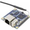
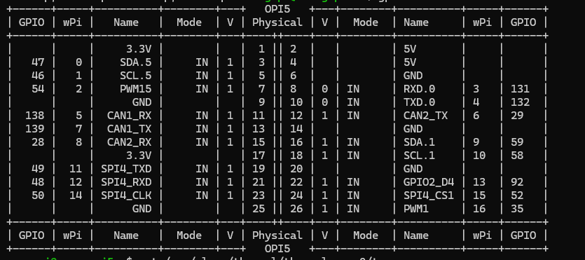
hello, i was trying to set up a 2 pin fan on my orangepi 5b and i connected it to pin 25 and 26 (GND and PWM1). When i first started this task, the output from gpio readall would show me all 26 pins on the board. As i was digging through some forums to try and get the PWM pin to operate as on/off, i came across wiringOP and when i installed it, the output of `gpio readall` changed to only show 8pins. I am unsure of what went wrong and why it only shows 8 pins. I tried removing wiringOP and it still has not made a difference. Thanks

-
Hi I'm using an Orange Pi PC Plus with a LoRa HAT (Semtech SX1278) connected via GPIO. The tool which uses this HAT connects directly to the SX1278 chip on the HAT, no protocoll like SPI is needed. I'm using it for several years on RaspberryPi's without problems. But with the latest ARMBIAN Image for the Orange Pi PC Plus Armbian_23.11.1_Orangepipcplus_bookworm_current_6.1.63.img.xz I have issues in this constellation. The tool can not contact the SX1278 via GPIO, said the tool developer. It seems like I have to activate the GPIO pins before. I've tried to find information about that, but without success. So I hope to find here more information and help. I have to use these hardware PINs (these are the PIN descritions on teh Raspberry Pi): MOSI SPI0_MOSI / GPIO10 (PIN 19) MISO SPI0_MISO / GPIO9 (PIN 21) SCK SPI0_SCLK / GPIO11 (PIN 23) NSS/Enable SPI0_CE0_N / GPIO8 (PIN 24) RST GPIO6 (PIN 31) Thanks in advance.
-
Looking at the new BPI M4 zero to replace a RPI zero. The official build listed does not have gpio turned or maybe just not built into the kernel. If I download the image from the BPI website it has it but it based on bullseye and the image is broke. I built my own image but still no go so I am not sure what is wrong. I have built images for other boards and projects with success so that's not the problem. I have a 3.5" TFT touch screen and some relays that I need to run along with a sensor.
-
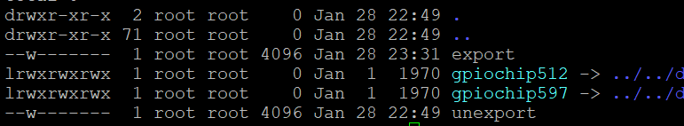
Yesterday, I tried to use the digital IO in my opi zero3, with the Python GPIO package from https://opi-gpio.readthedocs.io/en/latest/ by Richard Hull It depends on having sysfs files in /sys/class/gpio/ My original opi zero has these files and it works, but my opi zero3 doesn’t have these files I learned that /sys/class/gpio is created if the linux kernel is configured with a specific option ON, as suggested in the documentation: https://github.com/rm-hull/OPi.GPIO https://linux-sunxi.org/GPIO Also, a developer has made a change on the opi.GPIO project to support opi zero3 https://github.com/rm-hull/OPi.GPIO/issues/79 I will have time to try this tomorrow... but I want to ask: is anyone using GPIO in its most basic way? As reference: I saw this older thread about zero3's GPIO... https://forum.armbian.com/topic/31493-how-to-enable-i2c3-on-orange-pi-zero-3/ It is using leebobby's "armbian" image, with raspi-config, and wiringpi Using my original opi-zero, I never needed to use armbian-config to enable basic gpio and the python opi.gpio just worked as documented Note: the opi.gpio only claims to support basic gpio, not i2c. Update: these are interesting potential solutions and discussions (but they are all from before there was armbian for opiz3) https://www.reddit.com/r/OrangePI/comments/16vfa4g/orange_pi_zero_3_gpio_python_library/ https://github.com/eutim/OPI.GPIO https://www.reddit.com/r/OrangePI/comments/16ioyri/gpio_python_library_for_orange_pi_zero_3/ https://www.reddit.com/r/OrangePI/comments/18iveo3/how_to_control_gpio_pins_in_android_orange_pi/
-
Hi, Armbian_21.02.3_Odroidc1_focal_current_5.10.21 how do I find out which number do I need to provide to gpio export command? Let's say I have physical pin 16, which is labeled by the manufacturer as `GPIOX.5` or `102`. But that doesn't work with Armbian: echo 102 > /sys/class/gpio/export [ 1602.030617] export_store: invalid GPIO 102 How do I know the value to provide for /sys/class/gpio/export? # cat /sys/kernel/debug/gpio gpiochip1: GPIOs 413-428, parent: platform/c8100084.pinctrl, aobus-banks: gpio-416 ( |TF_IO ) out lo gpio-417 ( |usb-hub-reset ) out hi gpio-426 ( |c1:blue:alive ) out hi ACTIVE LOW gpiochip0: GPIOs 429-511, parent: platform/c1109880.pinctrl, cbus-banks: gpio-456 ( |regulator-tflash_vdd) out lo gpio-470 ( |PHY reset ) out hi ACTIVE LOW gpio-482 ( |cd ) in hi ACTIVE LOW gpio-492 ( |reset ) out hi ACTIVE LOW Thanks
-
 Hello Armbian Team, i have the wish for the integration of - GPIO Support for RockPi 5b to the Edge Kerne - dtb's which are aviable for Kernel 5.10.160 mostly importend for me are the UARTS ( if tryed to compile the DTS files form 5.10.160 for the 6.8.2 .. ends after sending some to the UART with a Kernel segfault 😞 ) Thanks a lot for the good Work 🙂 René
 -
I have Armbian up and running on a Rock Pi S with a PoE HAT. To enable the audio jack on the PoE HAT I had to run the following commands as mentioned on the official Rock Pi S PoE Hat wiki. # echo 15 > /sys/class/gpio/export # echo out > /sys/class/gpio/gpio15/direction # echo 1 > /sys/class/gpio/gpio15/value Once enabled, the audio works as needed. However, every time the device is rebooted I have to SSH in and run these commands again to re-enable audio out which is obviously not ideal. How can I persist these changes between reboots?
-
Armbian 6.6.16-sunxi64 (bookworm) on NanoPi NEO2 NanoHatOLED fails: - GPIO devices are missing; 2024-03-29 23:04:55 root@M-DNS:~# uname -a Linux M-DNS 6.6.16-current-sunxi64 #2 SMP Fri Feb 23 08:25:28 UTC 2024 aarch64 GNU/Linux Seems regression of earlier issue that had been solved: Would appreciate as GPIO will restored in kernel.
-
Hello I'm running the NAS on Orange PI 5. I've run Armbian with EDK2 from https://github.com/armbian/build/pull/5900. The system starts from SSD disk connected via PCIE card with 4 SATA ports. I wanted to run simple fan control via GPIO, but setting the value 1 or 0 on GPIO has no effect and the multimeter connected to GPIO always shows 2.85V. How I did it. I installed wiringOP as the manual says. I selected GPIO 0 and entered the commands gpio mode 0 out gpio write 0 0 I connected a multimeter to GPIO 0 but it always shows 2.85V when I did gpio write 0 1 the multimeter also shows 2.85V gpio readall shows 1 in column V when "gpio write 0 1" command is shows 0 in column V when "gpio write 0 0" command is Does anyone have an idea what I'm doing wrong?
-
 Hello, this is weird. With armbian 23.8.1 I can access the gpio-pins of the raspberry 4b. With (current) armbian 24.2.1 neither wiringpi (gpio -v) works nor any direct access (like echo "4" > /sys/class/gpio/export) The only difference I can find is the version of armbian. Please give me a hint on how to get gpio-access working with the current armbian. THX Edit: with raspbian it works (echo "4" > /sys/class/gpio/export and cat /sys/class/gpio/gpio4/value), so apparently I used the correct method.
 -
Description Enable uboot gpio command. This would allow to set up rk3318-box'es LED display in custom uboot script. For example, to show "boot", this snippet can be added (gpio pins and letter codes should be adjusted for different STB/LCD models): FD650_MODE_WRCMD='0 1 0 0 1 0 0 0' DISPON='0 0 0 0 0 0 0 1' FD655_BASE_ADDR='0 1 1 0 0 1 1 0' Z='0 0 0 0 0 0 0 0' B='0 1 1 0 0 1 1 1' O='0 1 1 0 0 0 1 1' T='0 1 0 0 0 1 1 1' setenv d0 gpio clear C22 setenv d1 gpio set C22 setenv LC gpio clear C19 setenv HC gpio set C19 setenv send 'run d0 LC; for b in $cmd; do run d$b HC LC; done; run HC d1' cmd="$FD650_MODE_WRCMD 1 $DISPON 1" run send cmd="$FD655_BASE_ADDR 1 $Z 1 $B 1 $O 1 $O 1 $T 1" run send How Has This Been Tested? Please describe the tests that you ran to verify your changes. Please also note any relevant details for your test configuration. [x] Compile and boot rk3318-box Checklist: [ ] My code follows the style guidelines of this project [ ] I have performed a self-review of my own code [ ] I have commented my code, particularly in hard-to-understand areas [ ] I have made corresponding changes to the documentation [ ] My changes generate no new warnings [ ] Any dependent changes have been merged and published in downstream modules View the full article
-
 Hi, I have orange pi 5. I searched all over internet for information how to set on startup/power on GPIO pins behavior, but i cannot find anything. Most of GPIO pins are set to IN mode 1. Sadly I need them to output mode 1. I am scared something could burn this way since i set them to though wiringPI after kernel boot sequence is complete. Can some one give information how I can set them up at earlier point when I power on the board? I found that DTB/DTS file could do it. But there is no clear information / pin addresses I should set. Thanks in advance! Regards!
 -
Hy guys i want to use a push button on my orange pi. if i press the button, the orange pi should run a script. i only use esp8266 with arduino tu create some interactive tools. does anybody know, how it works on the orange pi and which cheapy button you would prefer? i only want to run sh script, when the button will be press. thank you a lot!
-
 The pyA20 gpio library is quite famous when people start to play with gpios , spi or i2c on sunxi boards but mapping needs often adjustments to work on your own board. This situation is not really friendly for 'beginners'. pyGPIO should help to make armbian a little bit more 'IoT friendly'. I didn't touch the 'backbone' of pyA20, so the syntax should be similar to its original (except pinname when using port instead of connector). How can I use this library: Cause all of this boards have (more or less) the same pinheader (sometimes other pins are deployed on the pinheader) pyGPIO tries to unify the mappings, so that code can be shared and deployed on all boards without touching the code. The mapping follows the pin naming of the RaspberryPi (it's not because I think their naming is perfect, but it should be the easiest way to port code from the 'RPi world' to Armbian. What is done: -Initial support for: OrangePi Zero/PcPlus/Lite/Plus2E NanoPi Duo(with and without Minishield)/Neo Olimex Lime/Lime2/Micro (pins are not renamed PG10,PG11 etc. instead of GPIO2, GPIO3 etc. cause those boards doesn't have a 'RPi Pinheader' Templates for 24,26 and 40 'RPi compatible' pin header -Board detection (when using Armbian) to check if your board is supported -Manual assignment when your board is not supported (yet) or automatic board detection fails What is not done: Testing testing testing! Documentation Meaningful examples (still the originals from olimex which wouldn't work anymore) What do you need to test the Library: You need python-dev and the Library which you'll find on my GitHub page. The installation should be easy, just follow the instructions... sudo apt-get install python-dev git clone https://github.com/chwe17/pyGPIO.git cd pyGPIO sudo python setup.py install Testing is the part where I need help. I don't have most of the boards which are supported (only OPi0 and OPi Pc Plus). I tested I2C and GPIO on the OPi0, for all the rest, I need you as testers, bug hunters, and feedback. Here are two short python snippets which should do the exact same thing (once with connector, you have to run them as root or with sudo otherwise it would not work!): import os, sys if not os.getegid() == 0: sys.exit('start script as root') from pyGPIO.gpio import gpio, connector from time import sleep gpio.init() gpio.setcfg(connector.GPIOp7, 1) #pin 7 as output n = 0 while n < 5: gpio.output(connector.GPIOp7, 1) sleep(1) gpio.output(connector.GPIOp7, 0) sleep(1) n +=1 sys.exit('finished ;-)') and once with port: import os, sys if not os.getegid() == 0: sys.exit('start script as root') from pyGPIO.gpio import gpio, port from time import sleep gpio.init() gpio.setcfg(port.GPIO4, 1) #gpio4 as output n = 0 while n < 5: gpio.output(port.GPIO4, 1) sleep(1) gpio.output(port.GPIO4, 0) sleep(1) n +=1 sys.exit('finished ;-)') Annotation: When using NanoPi Duo you've to possibilities with or without Minishield. Pin name is the same on both possibilities but when using port but pin numbering when using connector: Minishield: 3.3V |1·| 5V GPIO2 I2C0_SDA |3·| 5V GPIO3 I2C_SCL |5·| GND GPIO4 |··| GPIO14 UART1_TX GND |··| GPIO15 UART1_RX GPIO17 SPI1_MOSI |··| GPIO18 GPIO27 SPI1_MISO |··| GND GPIO22 SPI1_CLK |··| GPIO23 SPI1_CS 3.3V |··| NC (on mini shield) Without (e.g. connector.J1p7 or connector.J2p5) : J1 J2 (UART0_RX) |1| microUSB |1| 5V (UART0_TX) |2| |·| 5V GND |3| |·| 3.3V GPIO3 (TWI_SCL) |4| |·| GND GPIO2 (TWI_SDA) |5| |·| GPIO4 (IR_RX) GPIO23 (SPI1_CS) |6| |·| GPIO18 (IOG11) GPIO22 (SPI1_CLK) |7| |·| DM3 D- GPIO27 (SPI1_MISO) |·| |·| DM3 D+ GPIO17 (SPI1_MOSI) |·| |·| DM2 D- GPIO15(UART1_RX) |·| |·| DM2 D+ GPIO14 (UART1_TX) |·| |·| RDN (CVBS) |·| |·| RDP (LINEOUT_L) |·| |·| TXN (LINEOUT_R) |·| |·| TXP (MICP) |·| |·| LED-LINK (MICN) |·| microSD |·| LED-SPD Buttons (bigger orange pi boards) are mapped, but I didn't test if it works (mapping here, if somebody is interested in testing them, see mapping.h of your board): {"BUTTON", { { "BUTTON", SUNXI_GPL(4), 1 }, { { 0, 0, 0} }, } },
 -
Hi, I am using Armbian (latest) image on Banana Pi CM4 and I don't have access to gpio493. I am getting the following error: And looks like gpiochip4xx is not available: When I modprobe this gpio number, I am getting following error: modprobe: FATAL: Module gpiochip493 not found in directory /lib/modules/6.7.2-edge-meson64 Could you please help, how can I enable gpio 493? Thanks

-
 Hi all, recently installed this on OPi5, i would like to learn more about how to start utilising the GPIO to sense something like temperature alert of some sort or be able to add to the inputs and make something happen like send email alerts when something is triggered.. any suggestions ? cheers
 -
Hi, does anyone know how to get this working please? Thanks.
-
Description As specified in PR https://github.com/armbian/build/pull/5967, there was a nasty mistake in rockchip and rk322x source files that were attempting to create two groups (gpio and i2c) on the building host instead of the built image. This caused the build system to crash when the groups were already present on the building host, which is totally not desiderable, and the intended feature was also broken. After some inspection, the groups were leveraged by a couple of udev rules to allow non-root users have access to gpio and i2c resources out of the box. This PR fixes the group creation on the target built image. Note: gpio and i2c gids starts from 900 because gids nearby 1000 are already taken by some existing services. Note 2: this supersedes https://github.com/armbian/build/pull/5967 which can be closed as well. Jira reference number AR-1935 How Has This Been Tested? [ ] Compile debian bookworm for rockchip family, verify the presence of groups in target image [x] Compile debian bookworm for rk322x family, verify the present of groups in target image Checklist: [x] My code follows the style guidelines of this project [x] I have performed a self-review of my own code [x] I have commented my code, particularly in hard-to-understand areas [x] I have made corresponding changes to the documentation [x] My changes generate no new warnings [x] Any dependent changes have been merged and published in downstream modules View the full article
-
Hello! On newer kernel (5.10.63+) gpio behaves strangely. Led connected to gpio pin blinking opposide status led. Also it break spi work. armbianmonitor logs https://paste.armbian.com/faqorefumi VID202304051140011.mp4
-
 Description Please include a summary of the change and which issue is fixed. Please also include relevant motivation and context. List any dependencies that are required for this change. Jira reference number [AR-9999] How Has This Been Tested? Please describe the tests that you ran to verify your changes. Please also note any relevant details for your test configuration. [x] Someone tested with rock5 Checklist: [ ] My code follows the style guidelines of this project [ ] I have performed a self-review of my own code [ ] I have commented my code, particularly in hard-to-understand areas [ ] I have made corresponding changes to the documentation [ ] My changes generate no new warnings [ ] Any dependent changes have been merged and published in downstream modules View the full article
 -
Hello, I'm using a BPI M2 Zero (with H3 Chip) to control two relays on CON2-P05 / PA11 and CON2-P03 / PA12. During the boot process there is a high level present at the pins, which is driving the relays. Is there a way to create a DTB overlay to drive the pins to a low level during boot. My userspace application uses libgpiod to control the pins. I'm familiar with compiling and activating overlays, i would just need help to write the correct .dts file. Thank you very much in advance
-
 Hi, I have a board Orange Pi Zero with modified PAs for power of WiFi module from PA20 to PA02, by soldering a connection on board. This is done to allow connection of I2C DAC. I see that board definition in 'u-boot/configs/orangepi_zero_defconfig' It uses dts definition of: 'arch/arm/dts/sun8i-h2-plus-orangepi-zero.dts' I need to modify one section of this dts file from: reg_vcc_wifi: reg_vcc_wifi { compatible = "regulator-fixed"; regulator-min-microvolt = <3300000>; regulator-max-microvolt = <3300000>; regulator-name = "vcc-wifi"; enable-active-high; gpio = <&pio 0 20 GPIO_ACTIVE_HIGH>; to: reg_vcc_wifi: reg_vcc_wifi { compatible = "regulator-fixed"; regulator-min-microvolt = <3300000>; regulator-max-microvolt = <3300000>; regulator-name = "vcc-wifi"; enable-active-high; gpio = <&pio 0 2 GPIO_ACTIVE_HIGH>; How can I do this and use armbian build script: compile.sh Thanks, Michal
 -
 If I connected the serial port with my device through GPIO pin 8 and 10 (UART_AO_A_TXD, UART_AO_A_RXD), the Radxa Zero with " Armbian 23.02.2 Jammy" failed to boot. If I removed my device from the serial port, zero can boot. After booting, I connected my device to the UART port, it worked well through /dev/ttyAML0. Any suggestions? Many thanks!
 -
Hello, I tried ` echo 463 > /sys/class/gpio/export ` and it build gpio464 folder under /sys/class/gpio , and I cat `value` file to check gpio status. It seems not work. The same gpio was working on Bananapi official debian and Ubuntu mate image. How can I solve this problem? Thanks