Search the Community
Showing results for 'ov5640' in topics.
-
Cons: Voltage regulation for CPUX. The way I understand the schematics and @TonyMac32 'confirmed' it. There's no dynamic voltage regulation for feeding the CPU with 1.1V/1.3V. IMO thermal behavior of the board has to be checked before the board gets 'official support'. Yet another H3 board... IMO there's 'not much' where this board shines for 'another H3 board'. Pros: eMMC additionally available Heatsink which covers RAM& CPU All USB are deployed on type A connector Questions: Did someone check their CSI connector? Schematics says: 'GC2035 200W'. What does this mean for DVDD voltage? (GC2035 needs 1.8V, OV5640 needs 1.5V). Does this board need a 'camera expansion board'? Seems that libre computer rushes with a lot of different SoCs to the market no (LeKartoffel months ago, Tritium and Renegade now). From what I see, they maintain their products not bad in terms of software upstream. Do the devs think the same? This would decrease the 'amount of work' to maintain armbian on this board a lot.
-
TL;DR: All available H3 boards do not differ that much. But the few differences sometimes really matter! The following is an attempt to compare the different available H3 SBC that are supported by Armbian. The majority of boards is made by Xunlong but in the meantime two more vendors started cloning the Xunlong boards (and also Olimex is preparing H3 boards as OSHW). Both Foxconn/SinoVoip with their Banana Pi M2+ and FriendlyARM with their NanoPi M1 tried really hard to copy everything as exact as possible (the so called pin mappings -- how the many contacts the used H3 SoC is providing are routed to the outside). All the boards share the same 40 pin GPIO header (trying to be compatible to the newer RPi boards) and since all the other pin mappings are also 99 percent identical you can for example boot a NanoPi M1 with an Armbian image for Orange Pi PC without loosing any functionality (except of camera module) and the same applies to BPi M2+ that will boot happily an Armbian image for Orange Pi Plus 2E (except of camera module and WiFi/BT) In fact all the various H3 boards just differ in a few details: Amount of DRAM No, Fast or GBit Ethernet Voltage regulator and 'thermal design' (responsible for performance in full load situations) Storage capabilities (pseudo SATA and eMMC or not) Count of available USB ports (with or w/o internal USB hub) Some additional features like camera modules, WiFi/BT and additional/optional connectors (here it's important to check for driver functionality/availability. If there's no driver providing the necessary functionality then these 'additional features' are pretty much useless -- camera connector for example) Why focussing on the H3 SoC for this comparison? Since some of these boards are priced pretty competitive Mainlining support for H3 SoC and these boards is progressing really nicely so we'll be able to run these boards with mainline kernel pretty soon (thanks to the great linux-sunxi community) 2D/3D/video HW acceleration is available with legacy kernels (again thanks to the great linux-sunxi community) The feature set is nice for many use cases (quad core SoC, GBit Ethernet and 4 useable USB ports on some boards make a really nice low cost/power server) It got somewhat confusing regarding the many available Oranges and now also the cloned Banana and NanoPi This is also in preparation of a broader overview of the capabilities of all the boards Armbian currently supports now focussing on the H3 family. So let's get into details: Amount of DRAM That's an easy one. The H3 SoC supports up to 2 GB DRAM. The available and announced boards use either 512MB, 1 GB or 2 GB DRAM (low-power DDR3L on the bigger Oranges and DDR3 on OPi One/Lite, BPi M2+ and NanoPi M1). In case you're using Armbian it simply depends on the use case. And also it's necessary to understand that Linux tries to use all your RAM for a reason: Since unused RAM is bad RAM. So don't be surprised that Armbian will eat up all your RAM to cache stuff which improves performance of some tasks but the kernel will immediately release it when other tasks have a demand for it. If still in doubt please enjoy http://www.linuxatemyram.com. If you want to use your boards with the unofficial H3 OpenELEC fork too please be aware that OpenELEC benefits from at least 1 GB RAM since then the whole filesystem remains in memory and no accesses to a probably slow SD card happen. Prior to jernej/OpenELEC and Armbian resolving the kswapd bug a few weeks ago the 512 MB equipped boards performed rather poor. But now it seems that the unofficial OpenELEC fork runs pretty well also on the boards with less available RAM. Whether 1 vs. 2 GB RAM make a difference absolutely depends on the use case and no general recommendations can be made. Since OpenELEC has been mentioned it should be noted that the current implementation of the unofficial OpenELEC port for H3 boards makes use of the cedarx-license-issues-library (no clear license preventing the use if you care about legal issues -- please have a look at http://linux-sunxi.org/Kodi for further details) Networking: The H3 SoC contains an Ethernet implementation that is capable of 10/100 MBits/sec Ethernet and also GBit Ethernet. A PHY (that handles the physical interconnection stuff) for Fast Ethernet is already integrated into the H3 SoC but to be able to use GBit Ethernet an external GbE capable PHY is needed (the RTL8211E used on all boards adds approx 1.2$ to the costs of the board in question). Most H3 boards use the internal Fast Ethernet PHY so wired networking maxes out at ~95 Mbits/sec. Orange Pi Plus, Plus 2, Plus 2E and BPi M2+ provide GBit Ethernet (+600 Mbits/sec with legacy and exactly 462 Mbits/sec with mainline kernel) while Orange Pi Lite saves an Ethernet jack at all. The good news: Even with the Lite you can use wired network adding a cheap RealTek USB3-Ethernet dongle like this which is confirmed to exceed 300 Mbits/sec in a single direction. The currently available boards have either no WiFi (NanoPi M1, OPi 2 Mini, One and PC), rely on RealTek 8189ETV (OPi 2, Plus, Plus 2), the newer RealTek 8189FTV (OPi Plus 2E, Lite, PC Plus) or a WiFi/BT combination: AP6181 is used on the BPi M2+ but the vendor didn't manage to get BT working at the time of this writing. Currently only jernej's OpenELEC fork and Armbian have a working driver included for the new 8189FTV chip on the fresh Orange boards that seems to perform quite ok and provides client/AP/monitor mode. Can't say that much about that since in my very personal opinion all these 2.4GHz onboard WiFi solutions are simply crap Voltage regulator and 'thermal design': This is a very important differentation: All Orange Pi boards use a programmable voltage regulator to adjust the voltage the SoC is fed with. The SY8106A used on every Orange except of One and Lite can be controlled though I2C and adjusts the so called VDD_CPUX voltage in 20mV steps. This is important since 'dynamic voltage frequency scaling' relies on the principle of providing less voltage to the SoC/CPU when it clocks lower. So when the board is idle also the supplied voltage will be reduced resulting in less consumption and also less temperature. Since H3 is somewhat prone to overheating being able to adjust VDD_CPUX is also important when we're talking about the opposite of being idle. The SY8106A equipped Oranges reduce very fine grained the core voltage when they start to throttle down in case overheating occurs under constant heavy load. As a direct result they will automagically perform better since reducing VDD_CPUX voltage also reduces temperature/consumption so both CPU and GPU cores in H3 due not have to throttle down that much. Quite the opposite with BPi M2+. For whatever reasons SinoVoip saved put a the same programmable voltage regulator on their board as OPi One, Lite and NanoPi have but does not implement voltage switching so H3 there will always be fed with 1.3V. In addition it seems 'Team BPi' didn't take care of heat dissipation through PCB design (it seems Xunlong added a copper layer to the PCB that helps dramatically spreading the SoC's heat) and so with BPi M2+ (and NanoPi M1 too) you have to be prepared that you need both a heatsink and a fan to let this board perform under full load since otherwise heavy throttling occurs or when you use a kernel that does not implement throttling (4.6/4.7 right now for example) be prepared that H3 gets either destroyed or will crash through overheating if you run something heavy on BPi M2+ or NanoPi M1. We're still investigating whether this crappy thermal behaviour might be related to DRAM also (DDR3 vs. low power DDR3L on the Oranges) It seems this thermal behaviour is not that much related to the DRAM type used but more to PCB design (maybe using large internal ground/vcc planes optimizing heat dissipation on Oranges. NanoPi M1 and Orange Pi One/Lite use a rather primitive GPIO driven voltage regulator that is able to just switch between 1.1V and 1.3V VDD_CPUX which already helps somewhat with throttling. A rather demanding benchmark using cpuminer (a bitcoin miner making heavy use of NEON optimizations and assembler instructions) that knows a benchmark mode where it outputs the khash/s rate. On the left OPI+ 2E with the superiour SY8106A voltage regulator switching CPU frequency between 1200 and 1296 MHz. On the right little OPi Lite with the SY8113B voltage generator able to switch between 1.1V and 1.3V and with slightly lower performance since throttling prevents clocking that high. And in the middle as only board with applied heatsink on H3 poor Banana Pi M2+ using the same SY8113B voltage regulator but always feeding the H3 SoC with 1.3V (for whatever reasons!). Storage capabilities: The H3 SoC doesn't feature native SATA capabilities so the 2 boards that have a SATA connector (Orange Pi Plus and Plus 2) implement that using an onboard USB-to-SATA bridge. Unfortunately the chip used there -- a Genesys Logic GL830 -- is horribly slow limiting sequential transfer speeds to 15 MB/s write and 30 MB/s read. It also does not support the USB Attached SCSI Protocol (UASP) so when using mainline kernel attached disks an especially SSDs couldn't show their full random I/O performance. Given that common USB-to-SATA bridges used in external USB enclosures show way better sequential performance (35 MB/s in both directions and close to 40 MB/s when using an UASP capable bridge together with mainline kernel) the SATA port on these 2 SBC can not be considered a feature worth a buy. Every H3 board has a TF card slot (Micro SD card) and some of the boards feature onboard eMMC storage. The H3 can cope with TF cards that are compliant to the SD, SDHC and SDXC standards so rather large cards with more than 64 GB capacity can also be used (be aware that there do not exist that much cards with a capacity larger than 128 GB. Chances are pretty high to get a counterfeit card especially when the price looks too good to be true ). You should also be aware that all H3 boards show the same sequential speed limitations (maxing out at ~23 MB/s) so choosing cards that are rated way faster aren't worth a buy. Better have a look at random I/O performance that is more important in most use cases. The eMMC used on various boards is pretty fast (sequential speeds maxing out at ~75 MB/s and especially random IO way faster than the fastest tested SD cards which is important for desktop useage and databases for example) so you don't make a mistake choosing any of the eMMC equipped H3 boards (BPi M2+, Orange Pi Plus, Plus 2, Plus 2E or PC Plus). You find detailed test results of current SD/TF cards as well as all the eMMC variants used in these two threads: http://forum.armbian.com/index.php/topic/954-sd-card-performance/ http://forum.armbian.com/index.php/topic/990-testers-wanted-sd-card-performance/ Count of available USB ports: The H3 SoC features 3 USB2.0 host ports and one USB OTG port. With Armbian we configure the OTG port as a host port that shows pretty similar performance so on some H3 boards (Orange Pi PC, PC Plus and Plus 2E) you can benefit from 4 USB2 ports that do not have to share bandwidth. Some other boards use an internal USB hub (Orange Pi 2, Plus, Plus 2) so the available USB ports have to share bandwidth in reality. Please keep that in mind when you compare the 4 USB Type A jacks OPi 2, Plus or Plus 2 feature (all being connected to a USB hub so having to share the bandwidth of a single USB 2.0 host port) with the 3 you can count on OPi PC, Plus 2E or NanoPi M1. On the latter boards you get full USB 2.0 bandwidth on each USB receptacle without the need to share bandwidth. BPi M2+ does also not use an internal USB hub but only exposes 2 USB host ports on type A receptacles and the 3rd host port only without ESC protection via soldering (but since this board shows such a terrible thermal design and is relatively overpriced compared to other H3 boards that doesn't matter that much) Additional features: The only board featuring a Bluetooth capable chip from BroadCom is the BPi M2+. Currently the vendor admits that BT is not working so better don't count on this feature to be ever available. Update: Jernej got BT already working in his OpenELEC fork so it's just a matter of time until it works with Armbian too. The H3 SoC is able to output/intercept additional signals, eg. analog audio, Composite video (TV out), IrDA that are present on most of the boards. On the Orange Pi One many of those interfaces are only present as solder points (a bit too tiny to be used by the average maker) and on some other boards they are not present at all (BPi M2+ for example has neither composite video nor analog audio) so always check first what you need or want to use. We have a nice sortable table in linux-sunxi wiki showing most of the important details: http://linux-sunxi.org/Table_of_Allwinner_based_boards Camera modules: Xunlong provides a pretty cheap 2MP camera module that should work with every H3 Orange Pi out there (they all have the necessary connector but for OPi One, Lite, PC and PC Plus you have to tell Xunlong that you also need a so called 'expansion board' that they ship free of charge if you add to your order that you need it. Starting with Armbian release 5.15 we also include an improved driver for this camera. Regarding current state of available camera modules for Oranges, BPi M2+ and NanoPi M1 please look through this thread: http://forum.armbian.com/index.php/topic/1213-ov5640-camera-with-orange-pi/?view=getlastpost
-
Hi @lex, To reach 60 FPS, or more, just changa VTS/HTS value. I created some tool (I launch it in DevC++) that shows what is the end FPS and some other parameters. Just play with the registers: #define MCLK (20*1000*1000) --> usually 24 MHz is used #define MCLK_DIV 1 #define REG_3034 0x18 #define REG_3037 0x4 #define REG_3036 (4*20) #define REG_3035 0x11 #define REG_3108 0x01 And VTS /HTS values here: hts_high = 0x07; // 0x380c hts_low =0xf4; // 0x380d vts_high = 0x07; //0x380e, vts_low = 0xac; //0x380f I have also noticed that almost all drivers are not appropriate for OV5640 (it seems they wrtitten based on OV5642 software application note - for example max lines is different for both sensors: 1964/1968). I found this doc for OV5640 and fixed some things. You can also find there 90 FPS for VGA configuration: https://wenku.baidu.com/view/6b48a191f90f76c661371afa.html main.cpp
-
BTW, banana pi zero and nano pi air makes a perfect board for using OV5640 sensor, so i would like to ask @Robert LabTeam if you are going to share your work on the OV5640 to be able to reach 60 fps or 90 fps, will you?
-
@lvmc, You probably know there is no CSI/VFE subsystem in kernel 4.xx , to have full control over DVP interface for OV5640 you should rely on legacy kernel or develop your own subsystem which is... well... overkill. As a start, you could look into ./config/boards and change from a current H2 board config file and modify/add information, since all H2 seems to be very similar with little changes. You just need to find the correct gpio/port pins for the ./config/fex (if legacy). Nora Lee from Foxconn has always provided information when asked, seems to be part of the business, need more information... just ask me. (you get the picture! ) Hope this helps.
-
@tkaiser it works with both SinoVoip's OV5640 or own custom module.
-
So you combine it with SinoVoip's OV5640 or another module?
-
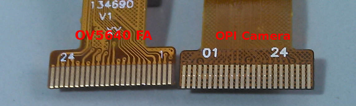
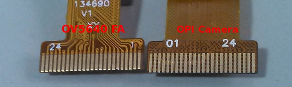
Don't try to use FA OV5640 on Opi Extension , you will possibly damage the sensor. The pins are not compatible.
-
Hi, my module arrived, but your VGA is better than mine... I just got nothing til now )-: Did you get a OV5640 working on an Orange Pi? An other idea is to have a look into the Orange Pi plus schematics. the plus does not need the extension board, so it seems to be integrated... The filename is : orangepi-plus-h3-v1_1.pdf greetings Thorsten
-
Some additional points. For the OPI one you have to enable one of the PIO pins otherwise the camera remains off. Ensure that the cable is conductor side down on the camera adapter and facing the bottom of the OPI board. This means with boards and cable lying flat the camera is looking down at the desktop, Despite this the modules I have will not run correctly at anything above VGA resolution IMVHO the FriendlyArm boards with the 5MP OV5640 sensor are far easier to wrangle and do work at advertised resolutions/speeds. # run before you modprobe gc2035! sudo sunxi-pio -m "PG11<1><0><1><1>"
-
Hello Thorsten No to reverse engineering. And the camera (connected to an OPI One) seems unwilling to work at anything better than VGA resolutions. By comparison the FriendlyArm OV5640 based module is a paragon of stability and quality, a much better bet IMHO. BR
-
I think you mean HW encoding? If you mean Encoding , yes guvcview uses SW encoder and i think HW encoder will take some time to be implemented unless someone else do it, or you can use ffmpeg to encode and render it with vdpau. Edit: guvcview uses SDL 1.2 for rendering it on screen, you can check if the SDL is set to use HW, if i recall correctly i tried to use SDL 2.x and got worse rendering speed. Regarding v4l2-ctl there is a user who got this working and also got higher FPS (for OV5640). Please ask him if he can share the code:
-
Yep, already have twi_used=0 for twi2. Or were you saying to turn it on? Digging around the kernel and putting various debug statements in various places, I have been able to trace it down to this section of the bsp_clie.c file with a switch on frame_info->pix_ch_fmt[ch] inside the for loop case PIX_FMT_YUYV: if(bus_pix_type[ch] == BUS_FMT_YUYV) { fmt_cfg[ch].input_fmt = CSI_RAW; fmt_cfg[ch].output_fmt = (is_buf_itl[ch] == 1)? CSI_FRAME_RAW_8:CSI_FIELD_RAW_8; } else { printk(KERN_CRIT "[DGM] bsp_csi_set_fmt Failed on frame_info->ch_field (PIX_FMT_YUYV) idx: %d; bus_pix_type 0x%x; case 0x%x, bus_info->bus_ch_fmt 0x%x\n", ch, bus_pix_type[ch], PIX_FMT_YUYV, bus_info->bus_ch_fmt[ch]); return -1; } break; Tracing this back up into the vfe.c file, it looks as if frame_info->pix_ch_fmt[ch] is getting set based on a called to pix_fmt_v4l2_to_common() and the bus_pix_type[ch] comes from find_bus_type(), and the value that gets passed into that comes from bus_pix_code_v4l2_to_common() (and has a value of 0x2006, or BUS_FMT_UYVY8_2x8). I've grabbed the vfe.c and the ov5640.c files from the lichee kernel and put those into my armbian source tree before building and that does seem to get me past this issue, but I now have problems when trying to map the memory for the buffers.
-
Perfect. Thanks very much. Help greatly appreciated. For anyone else with the same issue I've attached a working FEX file. Back up the existing copy (/boot/script.bin), compile with fex2bin script.fex > script.bin and copy the new file into /boot. Reboot, modprobe the OV5640 and vfe_v4l2 modules. You should then have a /dev/video0. v4l-utils contains v4l-ctl. Trying to get a control listing will end up with a load of errors in dmesg but this is a driver shortcoming, not a hardware problem. The attached bitmap is a VGA sized snap. Note it is backwards script.fex desktop.bmp
-
This is for the GC2035 (OrangePi camera) sensor, you need OV5640 configuration, please read @lordofduct answer in this thread.
-

OV5640 on OPI0+: How to reach higher fps and color spaces
@lex replied to Robert LabTeam's topic in Allwinner sunxi
I asked this question on linux-sunxi googlegroups mailing list long time ago and nobody answered, during this time i worked on available stock drivers (ov5640 and gc2035) and improved it as i could. The lesson i have learned so far: * You need NDA to have access to some documentation / undocumented features of the chip * Is is about Data transfer, you can't have a 60 FPS (1920x1080) rate when there is no bandwidth available for that, i think here is where MIPI helps. I think you have answered your own question, it only about to set the right registers and increase Data transfer on the CSI/VFE subsystem. You already have the right registers on your STM32Fx so it just a matter of setting it on the current available driver. I would love to see even a 30 FPS (1920x1080) on my A64 (5 times faster than STM32Fx ???). I am looking forward to seeing your results, please post your progress. -
Apologies if this is a FAQ. I'm trying to diagnose OV5640 camera issues on my NanoPiM1 using the headless xenial distro with the legacy kernel. Is there an accessible version of the compile.sh that built this distro? I'd really prefer to be able to rebuild all on a proper desktop machine ... TAIA Jerry. nanopim1:~$ uname -a Linux nanopim1 3.4.113-sun8i #28 SMP PREEMPT Thu Feb 2 02:01:28 CET 2017 armv7l armv7l armv7l GNU/Linux
-
Greetings. I cannot get my M1 to recognize that the cam500B is attached at all. I am using the Ubuntu xenial headless image here: https://dl.armbian.com/nanopim1/Ubuntu_xenial_default.7z Anyone got a quick solution before I start hacking into the VFE code? The `[ISP] isp platform_id = 5!` is unusual ... TAIA Jerry ~$ uname -a Linux nanopim1 3.4.113-sun8i #28 SMP PREEMPT Thu Feb 2 02:01:28 CET 2017 armv7l armv7l armv7l GNU/Linux nanopim1:~$ lsmod Module Size Used by vfe_v4l2 1015779 0 videobuf_dma_contig 3509 1 vfe_v4l2 videobuf_core 14682 2 vfe_v4l2,videobuf_dma_contig ov5640 42234 0 vfe_subdev 4507 2 vfe_v4l2,ov5640 cci 22800 2 vfe_v4l2,ov5640 vfe_os 4277 3 cci,vfe_v4l2,vfe_subdev pcf8591 3363 0 bmp085 3487 0 btrfs 712409 0 nanopim1:~$ dmesg | tail [ 59.082564] [OV5640@lex]init_sensor - frame_rate: 0, max_win_size: 11 [ 72.413069] [ISP] isp platform_id = 5! [ 72.420133] [VFE_ERR]Error registering v4l2 subdevice No such device!
-
Hi, I want to apply some changes to default camera driver (ov5640) to get 60-90FPS, so I just need to change same initialization values in .c file. Now, I compile a whole armbian after patching the .c file to get driver (.ko file). Is there quicker way to obtain the driver without compiling a whole armbian (just get .ko file)?
-
It looks like the function that sets the brightness does nothing. https://github.com/friendlyarm/linux-3.4.y/blob/nanopi2-lollipop-mr1/drivers/media/video/ov5640.c#L1528 Maybe I'm reading it wrong and brightness is a "standard" value that v4l2 controls. I'm still digging in to the code to understand it. To answer the original question, brightness for v4l2 drivers is supposed to be controlled with v4l2-ctl. eg v4l2-ctl -c brightness=200.
-
I tried to recompile ov5640 and vfe modules with DEV_DBG_EN 1 and now after commands modprobe ov5640 vfe_v4l2 I can see next: dmesg | grep VFE [ 1621.705770] [VFE]Welcome to Video Front End driver [ 1621.706258] [VFE]pdev->id = 0 [ 1621.706270] [VFE]dev->mipi_sel = 0 [ 1621.706278] [VFE]dev->vip_sel = 0 [ 1621.706285] [VFE]dev->isp_sel = 0 [ 1621.712469] [VFE_WARN]vfe vpu clock is null [ 1621.720171] [VFE]..........................vfe clk open!....................... [ 1621.720442] [VFE]vfe_init end [ 1621.730275] [VFE]probe_work_handle start! [ 1621.730308] [VFE]v4l2 subdev register input_num = 0 [ 1621.730320] [VFE]vfe sensor detect start! input_num = 0 [ 1621.730337] [VFE]Find sensor name is "ov5640", i2c address is 78, type is "YUV" ! [ 1621.730350] [VFE]Sub device register "ov5640" i2c_addr = 0x78 start! [ 1621.730366] [VFE]v4l2_device_register_subdev return 0 [ 1621.730377] [VFE]registered sensor subdev is OK! [ 1621.730385] [VFE]Check sensor! [ 1621.743731] [VFE]mclk on [ 1621.860358] [VFE]mclk off [ 1621.872420] [VFE]Sub device register "ov5640" is OK! [ 1621.872804] [VFE]V4L2 device registered as video0 [ 1621.872843] [VFE]..........................vfe clk close!....................... [ 1621.872866] [VFE]probe_work_handle end! [ 1621.881727] [VFE]vfe_open [ 1621.881754] [VFE]..........................vfe clk open!....................... [ 1621.881798] [VFE]vfe_open ok [ 1621.882233] [VFE]vfe_close [ 1621.882247] [VFE]vfe select input flag = 0, s_input have not be used . [ 1621.882269] [VFE]..........................vfe clk close!....................... [ 1621.882304] [VFE]vfe_close end and grep | ov5640 [ 1613.793181] [OV5640@lex]init_sensor - frame_rate: 0, max_win_size: 11 [ 1621.742431] [OV5640@lex]CSI_SUBDEV_PWR_ON! [ 1621.810043] [OV5640@lex]sensor_init 0x0 [ 1621.848152] [OV5640@lex]write sensor in function sensor_init=OK [ 1621.849336] [OV5640@lex]sensor_init DONE - exit [ 1621.849347] [OV5640@lex]CSI_SUBDEV_STBY_ON! [ 1621.849355] [OV5640@lex]sensor_s_release_af [ 1621.860033] [OV5640@lex]disalbe oe! [ 1621.730337] [VFE]Find sensor name is "ov5640", i2c address is 78, type is "YUV" ! [ 1621.730350] [VFE]Sub device register "ov5640" i2c_addr = 0x78 start! [ 1621.872420] [VFE]Sub device register "ov5640" is OK! Then I try to streaming video with mjpg-streamer but unsuccessful dmesg | grep VFE and grep OV5640 shows [ 1737.333490] [VFE]vfe_open [ 1737.333514] [VFE]..........................vfe clk open!....................... [ 1737.333571] [VFE]vfe_open ok [ 1737.512792] [VFE_ERR]bsp_csi_set_fmt error at vidioc_s_fmt_vid_cap! [ 1737.519970] [VFE]vfe_close [ 1737.519983] [VFE]vfe select input flag = 0, s_input have not be used . [ 1737.520063] [VFE]..........................vfe clk close!....................... [ 1737.520102] [VFE]vfe_close end [ 1613.793181] [OV5640@lex]init_sensor - frame_rate: 0, max_win_size: 11 [ 1621.742431] [OV5640@lex]CSI_SUBDEV_PWR_ON! [ 1621.810043] [OV5640@lex]sensor_init 0x0 [ 1621.848152] [OV5640@lex]write sensor in function sensor_init=OK [ 1621.849336] [OV5640@lex]sensor_init DONE - exit [ 1621.849347] [OV5640@lex]CSI_SUBDEV_STBY_ON! [ 1621.849355] [OV5640@lex]sensor_s_release_af [ 1621.860033] [OV5640@lex]disalbe oe! [ 1737.333646] [OV5640@lex]sensor_s_fmt [ 1737.333658] [OV5640@lex]capture_mode: 0 - V4L2_MODE_??? [ 1737.510072] [OV5640@lex]s_fmt set width = 640, height = 480 [ 1737.512425] [OV5640@lex]** pre_div = 3,mul = 70,sys_div = 1,pll_rdiv = 2,sclk_rdiv = 2 [ 1737.512439] [OV5640@lex]read pclk = 56000000 [ 1737.512452] [OV5640@lex]pv_fps(30) = pv_pclk(56000000) / ((vts_extra(0) + vts(984)) * hts(1896)) [ 1737.512465] [OV5640@lex]pv fps = 30 - ulres = 30 Please somebody help
-
I had tried to boot without camera and dmesg | grep OV5640 displayed: init_sensor - frame_rate: 0, max_win_size: 11 CSI_SUBDEV_PWR_ON! sensor read rety=2 error at sensor_detect chip found is not an target chip CSI_SUBDEV_PWR_OFF! And tried to boot with had connected camera then dmasg | grep OV5640 displayed next: init_sensor - frame_rate: 0, max_win_size: 11 CSI_SUBDEV_PWR_ON! sensor_init 0x0 CSI_SUBDEV_PWR_OFF! Then agian I may list /dev/video0 but no access to this device
-
Hello Christos & Igor Pecovnik, Thanks very much for all this great work! I am very NOOB to building kernels I wanted RT kernel to use with linuxcnc, specifically linuxcnc's 'hal' system Before building, I repaired 2 patch files that are missing 0x0a at end of file ( they produce err saying the file ends in middle of line, actually meaning at EOF ) friendlyarm_m1_gigabit.patch ( ends in 0x3a) ov5640-enhanced-device-with-vfe-drc-table-fix.patch (ends in 0x29) I repair by simply opening in nano and immediately saving. This action adds 1 0x0a byte to each file, and changes the timestamp. But, changing the timestamp creates another problem, the compile reports that it cannot update due to the change. I chose to continue Is this correct to add the missing 0x0a? Can I ignore the errors about ending in middle of line? I am trying to make preempt model 5, Christos said "Did a fresh OrangePi Plus2E image, legacy, Debian jessie, desktop, RT, but the SD boot gives this" Which preempt model did you succeed with? regards tomp
-
Attached is the FPC pinout for analysis. From the manual (CSI connector): Your link just confirm the sensor is GC0309 (the one attached to the LCD panel) and that is 0.3 MP sensor. If the metallic contacts face down, OV5640 seems to fit but there is no OV5640 driver in the kernel only OV5642. But i am not sure the connector representation is at the board side or at the LCD side (that would means it needs an extension/conversion of signals), i leave this review to the HW guys.

-

BPi-M2+ Problem to pair bluetooth speaker in command line
miguipda replied to miguipda's topic in Allwinner sunxi
Dear Arox, I am currently looking to the Orange Pi and the problem now (following the recommendations of tkaiser) is to find a board that will perfectly support armbian. A comparaison page should be good to make the best choice but does not exist on armbian. Than I could also encounter the same problem by choosing another board that may give some problems on specific hardware. Of course the well known RPi must solve this problem and of course I do not want to spend money to many boards to finally found that it should be better to first buy a RPi. Now I have the CSI OV5640 I will check wich board wille have enough RAM (1 Gb) and Bluetooth (to pair speaker) to allow me to use it as Home Assistant and door peehole (face recognition and motion detection : this is why I at least need 1 Gb of RAM). Have a nice day.