@lex
-
Posts
530 -
Joined
-
Last visited
Content Type
Forums
Store
Crowdfunding
Applications
Events
Raffles
Community Map
Everything posted by @lex
-
A little info for @Igor, kernel 4.14.14 runs the board at 35 ºC idle, i tested 4.15.18 (EOL) and it runs at 28 ºC.. pity is EOL..
-
Never mind, i missed spidev. Ok, the LCD displayed a blank screen when running ./lcd. Looks like something wrong with the wiring? * Info The latest build is a bit misleading... ./lcd Full screen updates max out at 23.92 FPS 2000 random rectangles in 17131 ms root@nanopineo2:~/SPI_LCD# uname -ra Linux nanopineo2 4.14.14-sunxi64 #10 SMP Thu Jan 25 20:42:04 CET 2018 aarch64 aarch64 aarch64 GNU/Linux root@nanopineo2:~/SPI_LCD#
-
@Larry Bank Here come the newbie questions: * I enabled spi in ArmbianExnv.txt i think and get this: root@nanopineo2:~/SPI_LCD# cat /boot/armbianEnv.txt verbosity=1 console=both overlay_prefix=sun50i-h5 overlays=usbhost1 usbhost2 rootdev=UUID=666159eb-f089-4881-b642-df9bfe4bdfc4 rootfstype=ext4 param_spidev_spi_bus=0 usbstoragequirks=0x2537:0x1066:u,0x2537:0x1068:u root@nanopineo2:~/SPI_LCD# ./lcd Error setting SPI mode Error setting SPI speed Failed to open the SPI bus Problem initializing spilcd library root@nanopineo2:~/SPI_LCD# What am I missing?
-
Great, testing your SPI_LCD with Armbian 5.38 latest build and will check if the wiring is correct then. Thanks for the hint. Will report the results.
-
Someone sent a week ago a couple of 2.8" TFT Display ili9341 and asked me to wire it to an H5 and make it work. I had some experience with the ST7789S with Nanopi NEO plus2 and that worked out of the box so i decided to use Nanopi NEO2 as a test bed and used the same wiring scheme. I have managed to wire it and although the FB is created and no error at all but the display is blank (black with no backlight enabled). The frame buffer is filled with information but not displayed. here is the wiring (NEO2): NanoPi Display 19 SPI_MOSI 21 SPI_MISO 23 SPI_CLK 22 LCD_D/C 24 LCD_CS 7 LCD_RESET 11 LED_EN GND VCC (3v3) Kernel 4.15 output: [ 1.396261] fb_ili9341 spi0.0: fbtft_request_one_gpio: 'reset-gpios' = GPIO203 [ 1.403505] fb_ili9341 spi0.0: fbtft_request_one_gpio: 'dc-gpios' = GPIO1 [ 1.410317] fb_ili9341 spi0.0: fbtft_request_one_gpio: 'cs-gpios' = GPIO67 [ 1.417213] fb_ili9341 spi0.0: fbtft_request_one_gpio: 'led-gpios' = GPIO0 [ 1.711586] graphics fb0: fb_ili9341 frame buffer, 320x240, 150 KiB video memory, 32 KiB buffer memory, fps=50, spi0.0 at 64 MHz I doubled checked the wiring, seems to be OK. Has anyone succeeded in using ili9341 with H5? Please share your experience, kernel version, Armbian version, whatever...
-

Orange Pi Zero Plus2 H5 hardware oddity in VDD_CPUX power circuit
@lex replied to 5kft's topic in Allwinner sunxi
Mine is missing too and i have possibly the second batch (very old) so it comes from the beginning... -
... better ask on another thread...
-
Not that i know. (AW chip). But there are other boards with MIPI interface (higher FPS) but with two or three times this price tag. Forgot to mention: You can check the CSI progress for the v3s here: https://groups.google.com/forum/#!topic/linux-sunxi/Cu5ldv_SzSc[26-50] I have read (somewhere and i can't remember where) this was tested on H3. Maybe you get inspired and try to build one image and push it to github and i try to help somehow.
-
No luck with NanoHat OLED that has I2C spare connector, can't connect a dupont connector there, argh...
-
This is all components soldered on the PCB if you mean to find if is those are wired.

-
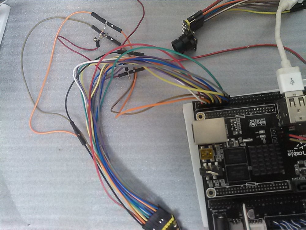
Ok, i think i understand the need of a resistor, but i thought these little devices already have it, no? Pity, This makes it impracticable for people with little skills or lack of knowledge to implement this. Long ago i struggled to wire a resistor to SDA and SCL lines to make an ov7640 to work with my cubieboard, as you can see a complete sh* but the final result worked. I can see a spare i2c connector on the NanoPi HAT, will do some checking and see if they are on the same bus line and try to learn a few things.
-
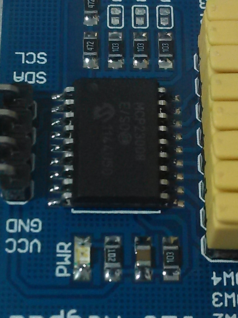
In case anyone curious, It works with WiringPi and is indeed MCP23008. This code excerpt works in 64-bit NEO2: wiringPiI2CWriteReg8(file, 0x09, 0x00); wiringPiI2CWriteReg8(file, 0x00, 0xF0); wiringPiI2CWriteReg8(file, 0x06, 0xF0); wiringPiI2CWriteReg8(file, 0x01, 0xF0); last = 0; while (1) { mask = 8; i = 0; while (i < 4) { // printf("mask: %c\n", ~mask & 0x0F); wiringPiI2CWriteReg8(file, 0x09, ~mask & 0x0F); val = wiringPiI2CReadReg8(file, 0x09); if (((val & 0xF0) != 0) && (val != last)) { printf("val: %d\n", val); last = val; } else { // printf("val?: %d\n", val); } mask = mask >> 1; i++; } usleep(100); j++; } close(file); I followed this guide: http://blog.thegaragelab.com/16-key-keypad-twintab/ Now i need to learn how i should wire different devices to share a single bus. Please share any thoughts. (for mere mortals...), lol
-
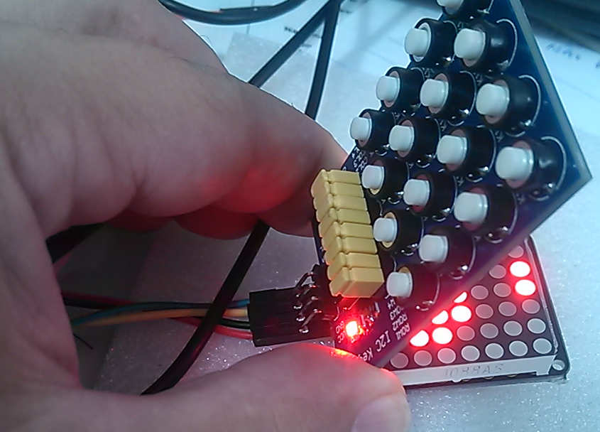
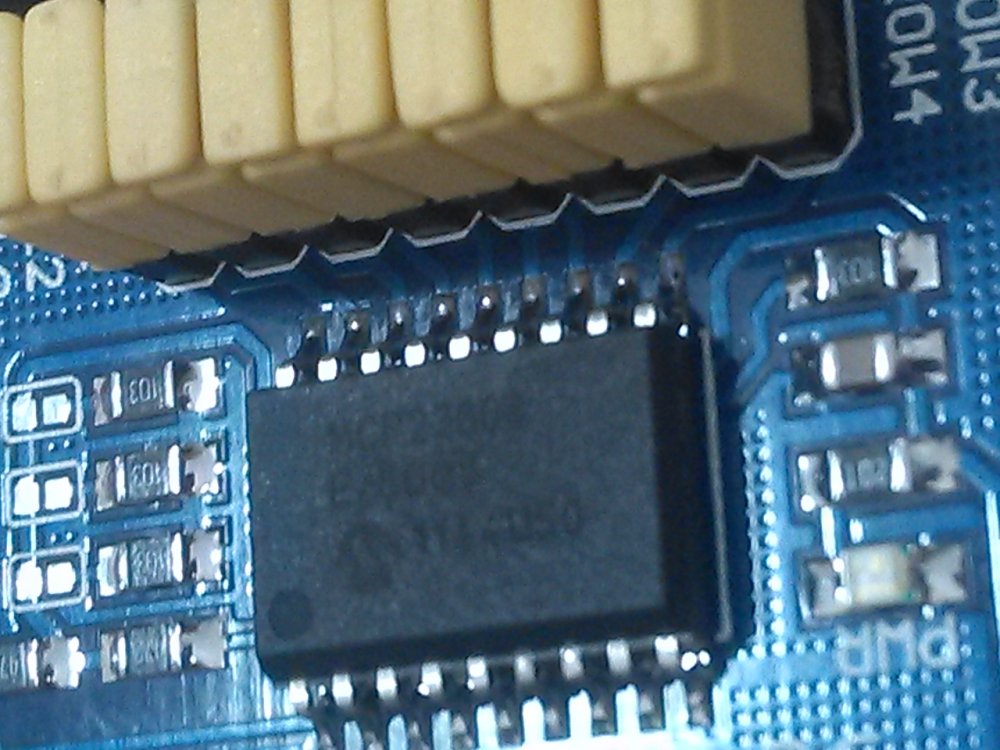
Sorry, my bad. I think my representation of the wiring is wrong, please see if this would make any difference: +-------------- / gnd -----< \ +-------------- +-------------- / 5v -------< \ +-------------- +-------------- / SDA-------< \ +-------------- +-------------- / SCL-------< \ +-------------- I think so, at least the i2c interface did not burn when attached to 5v and 3.3v. I derived right from the contacts of the first device attached and if i exchange places and i see always the first device. I tested the matrix with 3.3v and 5v and it worked with both. I have tried to read which chip is on the keypad, it is barely readable but seems to be * MCP23008. There are plenty of Py code out there but i am trying to port one in straight C which i am comfortable, but if someone already has one to share, please, do so. I will try to port one that i think is likely to work and share. My solder skills are very weak at the best, so do you guys have any suggestion for a good way to attach this in a more appropriate way? Thanks for all your reply. * PS: The picture of MCP23008 i see on internet looks a bit different .
-
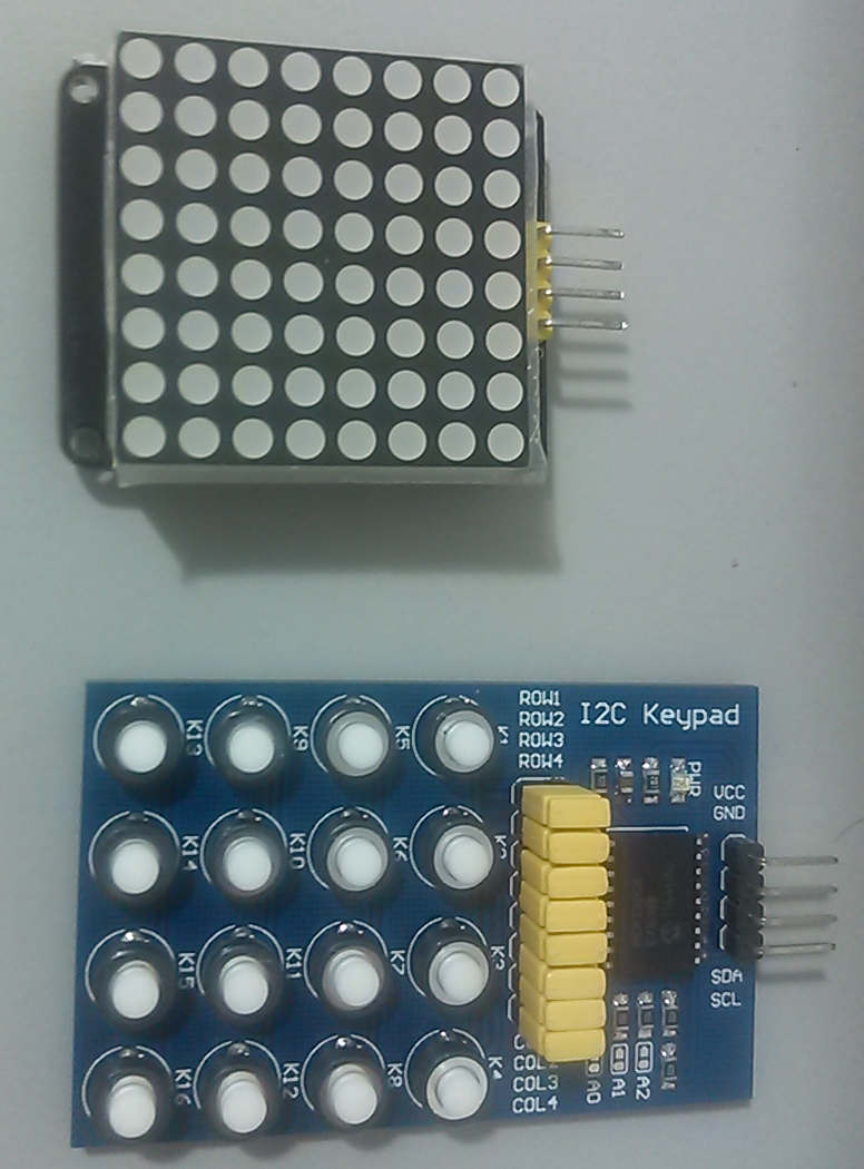
Today I received this two devices and started to play with i2c. I am new to i2c but I already figured out how to talk to each device alone but i want to use a single bus for both devices. The problem is when i connect both i can only see one device. Can someone point what is wrong with the way i am wiring it? The devices: The Matrix: sudo i2cdetect -y 0 0 1 2 3 4 5 6 7 8 9 a b c d e f 00: -- -- -- -- -- -- -- -- -- -- -- -- -- 10: -- -- -- -- -- -- -- -- -- -- -- -- -- -- -- -- 20: -- -- -- -- -- -- -- -- -- -- -- -- -- -- -- -- 30: -- -- -- -- -- -- -- -- -- -- -- -- -- -- -- -- 40: -- -- -- -- -- -- -- -- -- -- -- -- -- -- -- -- 50: -- -- -- -- -- -- -- -- -- -- -- -- -- -- -- -- 60: -- -- -- -- -- -- -- -- -- -- -- -- -- -- -- -- 70: 70 -- -- -- -- -- -- -- The keypad: sudo i2cdetect -y 0 0 1 2 3 4 5 6 7 8 9 a b c d e f 00: -- -- -- -- -- -- -- -- -- -- -- -- -- 10: -- -- -- -- -- -- -- -- -- -- -- -- -- -- -- -- 20: 20 -- -- -- -- -- -- -- -- -- -- -- -- -- -- -- 30: -- -- -- -- -- -- -- -- -- -- -- -- -- -- -- -- 40: -- -- -- -- -- -- -- -- -- -- -- -- -- -- -- -- 50: -- -- -- -- -- -- -- -- -- -- -- -- -- -- -- -- 60: -- -- -- -- -- -- -- -- -- -- -- -- -- -- -- -- 70: -- -- -- -- -- -- -- -- I am trying to wire this way: Board 5v -------------- matrix ----------------- keypad gnd ------------ matrix ----------------- keypad SDA ------------ matrix ----------------- keypad SCL ------------ matrix ----------------- keypad I don't have any documentation on the keypad. Maybe someone already worked with two devices on a single line, can you pinpoint what is wrong? or what should be done? I have read about a pull-up resistor but have no idea how to proceed.

-
Sorry, i wanted to help did not want to sound rude. Good luck.
-
if you attach a high-speed device, kernel (depends on which version) may or not detect your device That's exactly what you are doing wrong! Justa attach a USB keyboard and you will see a log, if NOT you have a faulty USB connector. Why not you tell which device you want to use?
-
@gdm85 Chances are you have a faulty USB socket. Both USB work with low-speed devices (that is why I asked your use case), if you attach a high-speed device, kernel (depends on which version) may or not detect your device. Works with 4.11.y, 4.14.y, 4.15.y with high-speed on some devices. See below: [ 370.698551] usb 2-1: new low-speed USB device number 2 using ohci-platform [ 370.945496] input: USB USB Keykoard as /devices/platform/soc/1c1a400.usb/usb2/2-1/2-1:1.0/0003:1C4F:0002.0001/input/input2 [ 371.006119] hid-generic 0003:1C4F:0002.0001: input,hidraw0: USB HID v1.10 Keyboard [USB USB Keykoard] on usb-1c1a400.usb-1/input0 [ 371.020708] input: USB USB Keykoard as /devices/platform/soc/1c1a400.usb/usb2/2-1/2-1:1.1/0003:1C4F:0002.0002/input/input3 [ 371.080155] hid-generic 0003:1C4F:0002.0002: input,hidraw1: USB HID v1.10 Device [USB USB Keykoard] on usb-1c1a400.usb-1/input1 [ 431.591036] usb 2-1: USB disconnect, device number 2 [ 435.232021] usb 8-1: new low-speed USB device number 2 using ohci-platform [ 435.477981] input: USB USB Keykoard as /devices/platform/soc/1c1d400.usb/usb8/8-1/8-1:1.0/0003:1C4F:0002.0003/input/input4 [ 435.539589] hid-generic 0003:1C4F:0002.0003: input,hidraw0: USB HID v1.10 Keyboard [USB USB Keykoard] on usb-1c1d400.usb-1/input0 [ 435.554152] input: USB USB Keykoard as /devices/platform/soc/1c1d400.usb/usb8/8-1/8-1:1.1/0003:1C4F:0002.0004/input/input5 [ 435.613613] hid-generic 0003:1C4F:0002.0004: input,hidraw1: USB HID v1.10 Device [USB USB Keykoard] on usb-1c1d400.usb-1/input1
-
Do you want the OTG ( i think you are referring to microUSB ) to act as a Host? Can you describe your use case? I have read @Igor explaining somewhere on how to use the OTG as peripheral. Would not this suffice? https://github.com/friendlyarm/linux/blob/sunxi-4.11.y/arch/arm64/boot/dts/allwinner/sun50i-h5-nanopi-neo-plus2.dts#L413 I usually disable OTG, OTG enabled eats a lot of CPU and increases CPU temp. Sorry if I misunderstood, I am now very curious about this 2nd USB support.
-
Kernel: https://github.com/BPI-SINOVOIP/BPI-files/commit/4a955b91d05fc33099c2d5ed23257da351799f36#diff-5cc9f5b01a36dfa973531226f8915151L127 U-boot: https://github.com/BPI-SINOVOIP/BPI-files/tree/master/others/armbian/build/patch/u-boot/u-boot-sunxi * FYI: it does not mean their image will boot, but will pass u-boot SD card detection and will not stop right away, There will be the second part of the boot that your board will possibly hang (different pin configuration, etc...). You will only know when you get your serial debug log!
-
Sorry, I did not mean your SD slot is broken, just u-boot should not check for cd-changes, something like: pinctrl-0 = <&mmc0_pins_a>, <&mmc0_cd_pin>; BananaPi M2+. M2+ H5 and BananaPi Zero need this patch in order to detect SD card.
-
You have possibly run into this problem, just use another u-boot!
-
@dbelvede Today i played a bit with the 1706 version and managed to have full xorg-xserver just like in any ordinary pc. The possible solution is to have: # CONFIG_SUN8I_DE2_CCU is not set and only one /dev/fb0 , this way you don't need to fire startx, just let lightdm start the session and xorg. With this way you don't need to calibrate the touch. I have found GAMMA correction is wrong for xserver, image is too bright while is good for framebuffer, maybe you are using some other driver. @farfeduc You need to add the entries on the Device Source Tree for the kernel to load and probe the driver on kernel 4.x
-
GC2035 camera driver is unavailable at sunxi-next 4.13.6 kernel ?
@lex replied to informer15's topic in Allwinner sunxi
There is no CSI available for Kernel 4.x 4.1x yet, it is a WiP.