All Activity
- Past hour
-
Mainline? The one from MR / my previous message
-
So I received my USB-PD trigger board, set it to 15V and it does nothing, the situation is still the same. I also ordered a USB tester to see the voltage and amperage, basically the board never draw more than 3 to 4W With Aarch64 UEFI image with EDK2 on the SPI flash, Linux starts to boot but then fails and I get a black screen
- Today
-
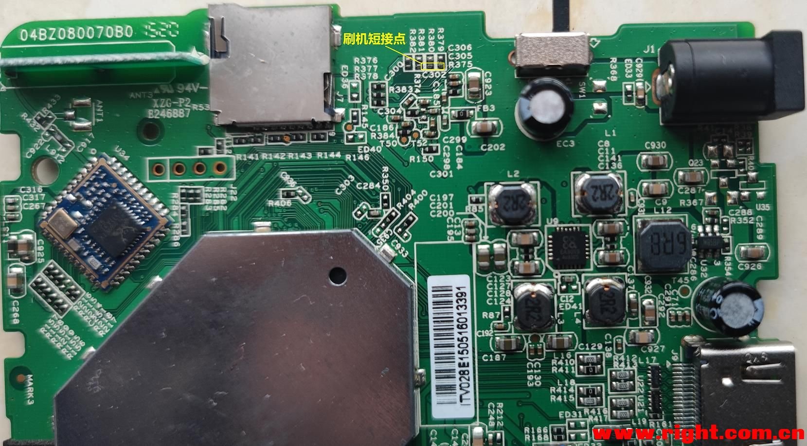
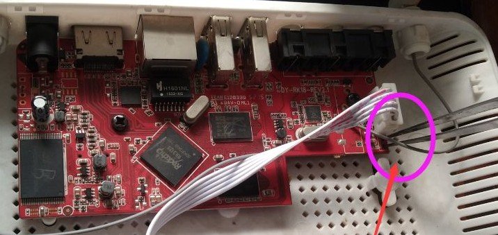
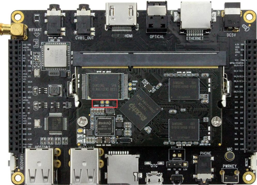
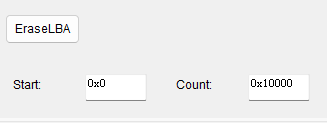
After finally getting my TV box to boot Armbian, I'd like to provide some beginner-friendly pointers in addition to @Chiều Nhạt Nắng's installation note 4.2, Full install to NAND / eMMC: As someone who's completely new to Android TV box modding, this step took me a while to get through. What it actually means is not to literally boot your TV box into its original firmware, but to enter either Loader Mode or Maskrom Mode. If you've built or tried to poke around your PC, they are sort of like the BIOS or UEFI (technically BIOS and UEFI live on the motherboard, not CPU... but I digress), or if you have done Nintendo Switch modding, it's like entering RCM. It's not the guide's fault because there are so many ways to get your chip to enter a "maintenance/recovery mode" on so many different boards even with the same chip, it's basically impossible to list all the ways to put it into a malleable state. The way to enter Loader or Maskrom mode typically requires you to do something to the TV box while it is actively booting up, which will interrupt the process and enter the respective mode. For my TV Box (2016 - 2020 ish, Huawei EC6108V9A, RK312X), to enter Loader Mode, I need to repeatedly tap the "Front Page" or "Home" button on my TV box remote as soon as I connect the OTG USB port to my PC (the OTG port is typically the USB port that's the closest to the Ethernet port), I didn't need to plug in the barrel power connector since the board draws power through the same USB connection. If you found yourself in an Android system recovery <3e> page, this is not what we want, you might be tapping the wrong button like "Standby" or "Sleep" button. For my board, once I successfully enter Loader Node, aside from the Windows notification and the Bold text saying "Found ____ Device" at the bottom of the RKDevTool/AndriodTool, it was also showing a static logo screen through HDMI. If you do not have the TV Box's remote, or if you have messed up the install and have to redo, you will almost definitely need to take apart the Box's outer shell and gain access to the PCB itself to enter Maskrom Mode instead. (Images found online) To enter Maskrom Mode, you will need to short two specific pins (or pin holes, or capacitor pads like the first image) as you plug the USB connector from the PC to the USB OTG port on your board (The official way is to short Clock (CLK) to Ground (GRD or any metal connector housing) but good luck finding those if they're not labeled). In my experience, tweezers are the best for this. Since everyone's board looks different, there are different ways to do it, but do not try to short anything on your board before you're absolutely certain that the image of the board matches the one on your hand exactly. Unfortunately these info are incredibly niche and hard to find, your best bet is to search your TV Box's model number along with your chip's name (RK3128 in our case) on google and bilibili, there's a good chance you'll end up on a Chinese forum and have to dig through it with google translate. (Do NOT take an AI's word for it!) In case the first step in the quote isn't clear enough, you have to click the EraseLBA button after typing in these addresses below it to erase sectors. It is also worth noting that you have to be in Loader Mode to EraseLBA or use any "Read____" buttons. If your device is in Maskrom Mode because you lost the remote or botched an install, you can't directly do all that aside from Download Image. The workaround is to hit the "..." button to the right of "Boot:", select rk3128_loader_v2.12.263.bin and hit Download. Now you can use most of the Advanced Functions while in Maskrom! In Chieu's attached image for this step, there is actually an error. If you are using the files from their 20260430 release (A26-release-20260430.zip), you will need to set Boot sector's address at 0x00006000, NOT 0x00010000. I strongly encourage you to open parameter.txt and verify the addresses yourself. My setup looks like this: 0x00000000 | Loader | rk3128_loader_v2.12.263.bin 0x00000000 | parameter | parameter.txt 0x00002000 | uboot | uboot.img 0x00004000 | trust | trust.img 0x00006000 | root | armbian_rootfs_26.2.img By the way, you can click on the empty box to the right of paths to find the files. Right click - Del item to delete any extra default entries you don't need. Now before you click Run, I strongly recommend you to connect the board to a monitor/TV via HDMI and your router via Ethernet with known good cables/connections! Your board's first boot into Armbian happens immediately after Download Image finishes, therefore it's incredibly difficult to monitor the progress without them. I'm honestly not sure if the setup can complete without Ethernet because I tried to flash my board without connecting Ethernet twice and failed twice. Miscellaneous Notes: If you're 100% positive that you have done the steps to enter Loader Mode or Maskrom Mode correctly but your PC is refusing to pick up the connection, try installing the driver "Rockchip_DriverAssitant_v4.2" (should be the first result on google). Some online sources might tell you to diagnose via UART with a USB-to-ttl adapter. It did not work on mine (was completely silent during boot). Conversely, not seeing anything from UART doesn't necessarily mean your board is bricked. The board should always be able to enter Maskrom if you have access to the PCB. After your board has gone through the first boot, you will see a prompt on the HDMI output asking you to set a password for the root user. You can connect to the board via SSH at this point with IP address shown during the boot sequence; you do not need to connect a physical keyboard to the board. A handy software to manage all your UART and SSH connections is MobaXterm. The settings are straightforward and there is a portable version if you don't like installing stuff. From OP's screenshots I think Chieu is using it too!

-
Hi, take a look at the build doc: https://docs.armbian.com/Developer-Guide_Build-Preparation/ You could try to build the kernel only, typically you get the latest version of the stable branch ./compile.sh kernel EXPERT="yes" BOARD=helios64 ARTIFACT_IGNORE_CACHE='yes' BRANCH=current
-
I am encountering similar issue in Allwinner-H618 based Kickpi-K2B board. Over the time, the video play stops with frozen frame display. The freeze is caused by the audio clock drifting from the video clock over time — and that drift happens during the video segments. have you (anyone) found the solution for this?
-

Gaming experience with Orange Pi 5 (RK3588) on Armbian
KhanhDTP replied to KhanhDTP's topic in Orange Pi 5
@Alex Ling That's weird. It's about 15% performance bump in theory. How GPU lock was show in...like Mangohud? -

SATA hard drives on Odroid-HC4 (OpenMediaVault works!)
BigHeadMode replied to BigHeadMode's topic in Odroid C4
I tried editing /boot/boot.cmd and recompiling. my changes did persist (I saw 'echo' worked) but it doesn't seem like my scsi scan trick worked. interrupting boot and just going straight into the above steps worked. so i think I need to edit boot.cmd to skip all the boot code for hc4 and just 'scan' then 'boot'. https://docs.armbian.com/User-Guide_Advanced-Configuration/ -

Gaming experience with Orange Pi 5 (RK3588) on Armbian
Alex Ling replied to KhanhDTP's topic in Orange Pi 5
@KhanhDTP, I've tried the 1GHz GPU patch but so far I do not see much performance boost with it. I tested Silk Song, Hitman: Absolution, Mario Kart 8 -
Still doesn't work for me.. USB works fine, only wifi is bugging and I don't have any other wifi card # sudo cp aic_btusb.ko aic_load_fw.ko aic8800_fdrv.ko /lib/modules/$(uname -r)/kernel/drivers/net/wireless/aic8800 # sudo depmod -a depmod: ERROR: failed to load symbols from /lib/modules/7.1.0-.ko: Invalid argument l/drivers/net/wireless/aic8800/aic_btusb.ko: Invalid argument-rc4-next-20260518-edge-rockchip64/kernel/drivers/net/wireless/aic8800/aic_btusb.ko: Invalid argument # sudo rm /lib/modules/7.1.0-rc4-next-20260518-edge-rockchip64/kernel/drivers/net/wireless/aic8800/aic_btusb.ko # sudo depmod -a depmod: ERROR: failed to load symbols from /lib/modules/7.1.0-aic8800/aic_load_fw.ko: Invalid argument depmod: ERROR: failed to load symbols from /lib/modules/7.1.0-rc4-next-20260518-edge-rockchip64/kernel/drivers/net/wireless/aic8800/aic8800_fdrv.ko: Invalid argument
-
Gaming experience with Orange Pi 5 (RK3588) on Armbian
KhanhDTP replied to KhanhDTP's topic in Orange Pi 5
@Alex Ling dxvk-stripped 3.0.0 https://github.com/khanh-it/dxvk/actions/runs/28276103625 -
Gaming experience with Orange Pi 5 (RK3588) on Armbian
Alex Ling replied to KhanhDTP's topic in Orange Pi 5
@KhanhDTP, thanks for the info. Great news! I'll try it. Have you tried the new dxvk 3.0 release? - Yesterday
-
Could you provide more detailed instructions? I tried methods 4.1 and 4.2, but neither worked: with 4.1, the board wouldn't boot from the USB to install Armbian, and with 4.2, there was absolutely no response—just a red light. I used RKDevTool with the file provided in your post. Images of my main https://ibb.co/VY4LKwrv https://ibb.co/x8SBCnm0 https://ibb.co/N28XWqxF
-
 Try this google AI search instead: create overlay on armbian orangepione for Nokia 5110 / PCD8544 LCD You might also need to add to armbianEnv.txt after enabling spi-spidev root@orangepione:~# more /boot/armbianEnv.txt verbosity=1 bootlogo=false console=both disp_mode=1920x1080p60 overlay_prefix=sun8i-h3 rootdev=UUID=f39623a3-f9cf-4fa1-be36-6854d244c378 rootfstype=ext4 overlays=spi-spidev param_spidev_spi_bus=0 usbstoragequirks=0x2537:0x1066:u,0x2537:0x1068:u root@orangepione:~# On successful startup of spi you should have a device: root@orangepione:~# ls /dev/spidev0.0 /dev/spidev0.0 root@orangepione:~#
 -

Teclast T60 AI rooting + armbian possibility Allwinner A733
Taz replied to Taz's topic in Allwinner CPU Boxes
So the wifi works on my tablet and to get it working you need to compile dkms package from https://github.com/radxa-pkg/aic8800/releases i used aic8800-sdio-dkms_5.0+git20260123.5f7be68d-5_all.deb i got the firmware files from stock firmware. You'd want to do this on x86 machine you are preparing the image because you need internet probably for it. -
Do a PR.
-
Hi @cal5582, your options are (rising difficulty) Do not install updates Set linux-kernel packages on hold (apt-mark hold...) Make a dkms config for your extra drivers (see above, "b2c2-flexcop-usb") Make your own Debian repo for updates and change /etc/apt sources in userpatches/customize_image.sh Start contributing to Armbian and convince devs to include your changes to kernel cfg HTH // Sven-Ola
-
Use Armbian Imager to create SDcard with curent Release. Connect HDMI Monitor and USB Keyboard. Put Sdcard into sdcard Slot and Power the Box. Follow instruction on Monitor
-
 I ran memtester and found memorie errors, which is probably the cause of the problem I report med earlies. Hopefully this can be solved by changing voltage er timing settings.
 -

Rupa X88 Pro 13 - RK3528 board with images
SuLorde replied to fedes_gl's topic in Rockchip CPU Boxes
A question from a beginner: how do I install it to use it for the first time? Should I use a flash drive and Rufus, or is there another way? I didn't quite understand, and I couldn't find any clear information. -
Let me know. I had hopes the commiter would provide upstreaming effort proof but nothing there yet.
-
For a start it looks like you are wiring to spi0 and so fragment0 does not make sense. It also might be causing the pa14 pin problem as the op1 does not have an spi1. Pin pa14 is used on a uart output. I suggest you get rid of fragment0 and just use armbian-config to enable spi0.
-
Good find! Will look through that PR more closely this weekend. Thanks.
-
just wanted to ask, is there any way to recompile the included drivers in the kernel after a kernel update? for instance i built the intel xe and radeon drivers into my kernel when building this image, but the kernel updates from mainline apt seem to overwrite it and the drivers go away. even when dkms installed.
- Last week
-

IMX708/ Pi Cam 3 not initializing on Pi Zero 2W
Stuart Watt replied to Stuart Watt's topic in Raspberry Pi
That's very useful. I'm nowhere near as practiced with this, so it'll take some time to digest and plan a way forward. It does fit with what seemed to be the case, though: it's device-level issues. I'll start poking around in the specific device differences and see what shows. The great hint you've found is that this is likely affecting all CSI cameras, not just the IMX708. That's most useful. I'm not at all worried about networkmanager, because the only tweak I made in the custom build was to use systemd-networkd, which (for me, anyway) is more straightforward for embedded/minimal/CLI usage. What I haven't yet done, and probably should, is switch to debugging this in something more vanilla, like a Pi 4. At least then I can compile libcamera and friends directly on the device. The Zero 2W should be the same -- he says, hopefully. -
Greetings ### [Follow-up Update] Boot Deep-Dive via Cubie-A5E DTB Masking Following up on my previous boot freeze post, I (with some assistance from Gemini - who formatted this post) managed to force the Armbian kernel to initialize by masking the sister chip profile (`sun55i-a523-cubie-a5e.dtb`) over the broken `sun55i-t527-orangepi-4a.dtb` target and injecting `clk_ignore_unused` / `irqpoll` parameters. This got us past the initial handoff hang and successfully spawned the 8-core CPU array initialization and initramfs launch (`Run /init as init process`), but the system eventually hit a permanent deadlock during the device probe phase. I don't think I can get this to go any further without some many hours spent looking at how these things work and its currently 35 degrees C here in the UK so time for a beer methinks! #### Full Boot Log Paste Link: - this is the log before using irqpoll parameter (which eventually caused a deadlock) - I can post the irqpoll logs although i wouldn't have thought irqpolling is the way to go ? https://pastebin.com/TvxTxdbp ### Either way - having just read that this post refers to irqpoll then this is the boot logfile with irqpoll added an an extraparm https://pastebin.com/TNS3DDTC #### Key Technical Takeaways from the Log Dump: 1. **PMIC / I2C Communication Failures:** The kernel initializes the AXP717 and AXP323 power chips but encounters standard timeout errors right away: ```text axp20x-i2c 0-0034: AXP20x variant AXP717 found axp20x-i2c 0-0034: Failed to set masks in 0x40: -6 axp20x-i2c 0-0034: failed to add irq chip: -6 ``` 2. **MMC / Storage Controller Deadlock:** Because the AXP717 framework drops out and the Cubie pin definitions do not line up with the Orange Pi 4A's physical board wiring, the kernel enters an endless loop waiting for internal voltage rails (`cldo3` and `bldo1`) to power up the storage controller: ```text platform 4020000.mmc: deferred probe pending: platform: wait for supplier /soc/i2c@7081400/pmic@34/regulators/cldo3 platform 4021000.mmc: deferred probe pending: platform: wait for supplier /soc/i2c@7081400/pmic@34/regulators/bldo1 ``` This prevents the storage device slot from spinning up, trapping the system right as it attempts to mount the root filesystem. Hopefully this helps isolate the unaligned power configuration loops and clock tables in the current `armbian-imager` source profile for the OPi 4A!