usual user
-
Posts
538 -
Joined
-
Last visited
Content Type
Forums
Store
Crowdfunding
Applications
Events
Raffles
Community Map
Everything posted by usual user
-

How to use OrangePi 5 Plus's NPU for Image Generation?
usual user replied to Johson's topic in Beginners
FWIW, on my rk3588 devices the NPUs are working with recent mainline releases: [ 5.967316] [drm] Initialized rocket 0.0.0 for rknn on minor 0 [ 5.975499] rocket fdab0000.npu: Rockchip NPU core 0 version: 1179210309 [ 5.978652] rocket fdac0000.npu: Rockchip NPU core 1 version: 1179210309 [ 5.985602] rocket fdad0000.npu: Rockchip NPU core 2 version: 1179210309 This script runs the Mesa example with the latest available working versions: And with this script, the Mesa example runs, with a small adjustment, also with the TFLite successor LiteRT: A MediaPipe sample can also be set up easily: But unfortunately, the MediaPipe framework does not support the extended delegate functionality of LiteRT (TFLite). And therefore no NPU support. classification-3.11-tflite.logclassification-3.13-litert.logobject_detection-3.12-litert.log -
It works for me without the DT fix as well, but PCIe doesn't work for me at all, even with the referenced patch. But I suppose it's because the device discussed in this thread doesn't have any PCIe hardware support at all.
-
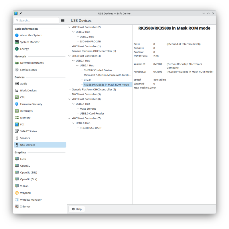
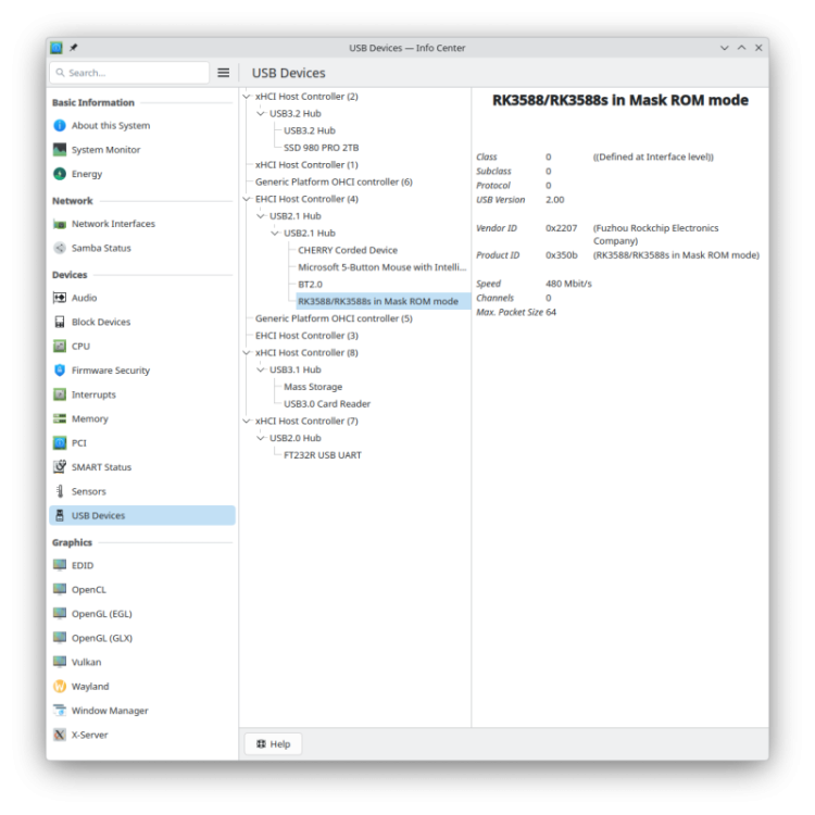
`idbloader.img` is device-specific code that is created from firmware build artifacts with U-Boot as payload using proprietary tools available only in binary form. SBC providers rarely offer ready-to-use code. I therefore prefer to load my firmware from microSD cards. Since it has apparently become increasingly common lately to provide only the MASKROM mode as the sole reliable recovery method, I have started building my firmware for Rockchip devices as RAM images as well. I can then simply upload them using MASKROM mode and start my work from there without having to rely on proprietary, binary-only tools.
-
Is see no significant differences: ******************************************************************************** ssd-006 Hardkernel ODROID-N2Plus CPU 0-1: performance 1000 MHz - 2016 MHz CPU 2-5: performance 1000 MHz - 2400 MHz GPU: performance 124 MHz - 799 MHz 6.16.0-0.rc1.17.fc43.aarch64 #1 SMP PREEMPT_DYNAMIC Sat Jun 14 11:19:02 CEST 2025 ******************************************************************************** 7z b 7-Zip 24.09 (arm64) : Copyright (c) 1999-2024 Igor Pavlov : 2024-11-29 64-bit arm_v:8-A locale=en_US.UTF-8 Threads:6 OPEN_MAX:1024 Compiler: ver:15.2.1 20250924 (Red Hat 15.2.1-2) GCC 15.2.1 : UNALIGNED Linux : 6.16.0-0.rc1.17.fc43.aarch64 : #1 SMP PREEMPT_DYNAMIC Sat Jun 14 11:19:02 CEST 2025 : aarch64 PageSize:4KB THP:madvise hwcap:8FF:CRC32:SHA1:SHA2:AES:ASIMD arm64 1T CPU Freq (MHz): 2092 2387 2384 2390 2361 2389 2388 3T CPU Freq (MHz): 282% 2239 296% 2352.. 6T CPU Freq (MHz): 538% 2040 497% 1893.. RAM size: 3740 MB, # CPU hardware threads: 6 RAM usage: 1334 MB, # Benchmark threads: 6 Compressing | Decompressing Dict Speed Usage R/U Rating | Speed Usage R/U Rating KiB/s % MIPS MIPS | KiB/s % MIPS MIPS 22: 7107 508 1362 6914 | 141426 488 2473 12058 23: 6459 494 1332 6581 | 136949 489 2421 11847 24: 6268 508 1327 6740 | 132118 485 2390 11593 25: 5695 515 1264 6503 | 127085 483 2343 11310 ---------------------------------- | ------------------------------ Avr: 6382 506 1321 6684 | 134394 486 2407 11702 Tot: 496 1864 9193 ******************************************************************************** ssd-006 Hardkernel ODROID-N2Plus CPU 0-1: performance 1000 MHz - 2016 MHz CPU 2-5: performance 1000 MHz - 2400 MHz GPU: performance 124 MHz - 799 MHz 6.18.0-0.rc3.30.fc44.aarch64 #1 SMP PREEMPT_DYNAMIC Mon Oct 27 21:17:35 CET 2025 ******************************************************************************** 7z b 7-Zip 24.09 (arm64) : Copyright (c) 1999-2024 Igor Pavlov : 2024-11-29 64-bit arm_v:8-A locale=en_US.UTF-8 Threads:6 OPEN_MAX:1024 Compiler: ver:15.2.1 20250924 (Red Hat 15.2.1-2) GCC 15.2.1 : UNALIGNED Linux : 6.18.0-0.rc3.30.fc44.aarch64 : #1 SMP PREEMPT_DYNAMIC Mon Oct 27 21:17:35 CET 2025 : aarch64 PageSize:4KB THP:madvise hwcap:8FF:CRC32:SHA1:SHA2:AES:ASIMD arm64 1T CPU Freq (MHz): 2365 2380 2383 2390 2389 2391 2388 3T CPU Freq (MHz): 277% 2162 274% 2095.. 6T CPU Freq (MHz): 533% 2021 508% 1926.. RAM size: 3737 MB, # CPU hardware threads: 6 RAM usage: 1334 MB, # Benchmark threads: 6 Compressing | Decompressing Dict Speed Usage R/U Rating | Speed Usage R/U Rating KiB/s % MIPS MIPS | KiB/s % MIPS MIPS 22: 6924 491 1373 6737 | 136783 473 2465 11662 23: 6586 495 1356 6711 | 141391 506 2418 12232 24: 6240 494 1359 6709 | 138310 510 2382 12137 25: 5912 507 1330 6750 | 127792 487 2337 11373 ---------------------------------- | ------------------------------ Avr: 6415 497 1355 6727 | 136069 494 2401 11851 Tot: 495 1878 9289
-
Expected default graphics acceleration for RK3588?
usual user replied to gpupoor's topic in Orange Pi 5 Plus
Right, I always use the same system with all my devices. Makes comparisons more meaningful. Only the loaded DT is the only difference. -
Expected default graphics acceleration for RK3588?
usual user replied to gpupoor's topic in Orange Pi 5 Plus
I have nothing to complain about and the VPUs are also working. classification-3.11.log fluster-run-odroid-m2-summary -
What do you expect from single lane M.2 PCIe2.0?
-
Expected default graphics acceleration for RK3588?
usual user replied to gpupoor's topic in Orange Pi 5 Plus
I have nothing to complain about. glmark2-wayland-odroid-m2.log vkmark-wayland-odroid-m2.log -
I was just about to rebuild the source package, but today's upgrade delivered everything turnkey since my development team was faster and had done everything for me. The previously referenced description does provide a working result, but it does not use the most current available releases. This script runs the NPU with the latest working releases: #!/bin/bash WORKBENCH="." python3.11 -m venv ${WORKBENCH}/python/3.11 source ${WORKBENCH}/python/3.11/bin/activate pip install numpy==1.26.4 pip install pillow==12.0.0 pip install tflite-runtime==2.14.0 TEFLON_DEBUG=verbose ETNA_MESA_DEBUG=ml_dbgs python ${WORKBENCH}/classification.py \ -i ${WORKBENCH}/grace_hopper.bmp \ -m ${WORKBENCH}/mobilenet_v1_1_224_quant.tflite \ -l ${WORKBENCH}/labels_mobilenet_quant_v1_224.txt \ -e /usr/lib64/libteflon.so deactivate classification-3.11.log
-
For rocket support you need at least 25.3. RTFM
-
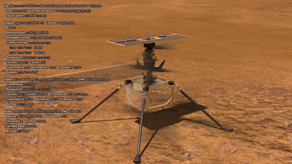
Official development for inclusion in upstream are carried out by working on the project's main branch. That's exactly what this pull request branch does by tracking the project's master tree. Applying commits to anything else is backporting. Backporting is possible, but you will have to deal with the consequences yourself that arise from your outdated versions lacking the functions required for your backport, and you may need to backport those as well. Since this project is a user program and not a framework with libraries that other programs depend on, it is solely the user who has to deal with it as a dependency in its use. At first, I also tried to use the sources of the current release version as a base, but since the commits couldn't be applied without errors, I simply built the current master branch. For the FFMPEG framework, this is already a whole different ballgame. There are many programs, which mpv is just one, that depend on the libraries and need to be rebuilt accordingly in case of an upgrade. Since my chosen distribution recently released ffmpeg 8.0 and thus made all dependent programs available accordingly, I just had to rebuild the ffmpeg package with the v4l2request support commits and put that in place. And since the commits could be applied to the current release sources without any errors, I didn't even need to switch to the master branch.
-
Just out of curiosity, why are you trying to backport the v4l2request support? Why not build the pull request tree directly: git clone --branch v4l2request https://github.com/philipl/mpv.git mpv-player-v4l2request
-
The 6.18.0-rc5 kernel doesn't require any patches, just have to been build with DRM_ACCEL_ROCKET.
-
Just for posterity. fluster-run-odroid-m2-summary
-
I have that line also: [ 0.496136] rockchip-pm-domain fd8d8000.power-management:power-controller: Failed to enable supply: -517 [ 0.938478] rockchip-pm-domain fd8d8000.power-management:power-controller: Failed to create device link (0x180) with supplier 2-0042 for /power-management@fd8d8000/power-controller/power-domain@8 [ 1.224290] rockchip-pm-domain fd8d8000.power-management:power-controller: Failed to enable supply: -517 [ 1.237338] rockchip-pm-domain fd8d8000.power-management:power-controller: Failed to create device link (0x180) with supplier 2-0042 for /power-management@fd8d8000/power-controller/power-domain@8 [ 1.294276] rockchip-pm-domain fd8d8000.power-management:power-controller: Failed to create device link (0x180) with supplier spi2.0 for /power-management@fd8d8000/power-controller/power-domain@12 [ 17.384495] rockchip-pm-domain fd8d8000.power-management:power-controller: sync_state() pending due to fdba4000.video-codec [ 17.385477] rockchip-pm-domain fd8d8000.power-management:power-controller: sync_state() pending due to fdba8000.video-codec [ 17.386457] rockchip-pm-domain fd8d8000.power-management:power-controller: sync_state() pending due to fdbac000.video-codec [ 17.387427] rockchip-pm-domain fd8d8000.power-management:power-controller: sync_state() pending due to fdc40100.video-codec But VPU seems to be working anyway:

-
If wired correctly, dmesg reveals the following: [ 5.967316] [drm] Initialized rocket 0.0.0 for rknn on minor 0 [ 5.975499] rocket fdab0000.npu: Rockchip NPU core 0 version: 1179210309 [ 5.978652] rocket fdac0000.npu: Rockchip NPU core 1 version: 1179210309 [ 5.985602] rocket fdad0000.npu: Rockchip NPU core 2 version: 1179210309 And when mesa is built with the rocket driver enabled, it can be used via teflon.
-
FWIW, HEVC support is queued for 6.19. With WIP patches on top, rkvdec2 is also available to me. With the gstreamer framework, this works for me out-of-the-box, as the necessary support has been available in mainline for quite some time. See video-pipeline.pdffor reference. I have already rebuilt the Huffman package with the patches mentioned above, but currently the developers of the distribution of my choice are busy rebuilding all packages that depend on it. As soon as the Huffman package is rolled out, I will start to see how HEVC performs with the FFMPEG framework.
-
Drop it in a Spoiler:

-
And since it contains no firmware payload output, no one can tell what you are running.
-
ffmpeg with hardware accelerated encoding
usual user replied to schunckt's topic in Software, Applications, Userspace
My rk3588 devices are e.g. exposing this: v4l2-compliance-odroid-m2.txt And here is the visualization of a video pipeline: video-pipeline.pdf Watch out for the v4l2slh265dec component. -
ffmpeg with hardware accelerated encoding
usual user replied to schunckt's topic in Software, Applications, Userspace
https://lore.kernel.org/linux-media/Z4e9wNxZjvnytXlL@pengutronix.de/ -
The mainline kernel has currently a shortcoming in USB-TYPEC support. FUKAUMI Naoki demonstrated a workaround for other devices that also works for the ODROID-M2.
-
Armbian with preinstalled OpenMediaVault (OMV)
usual user replied to Igor's topic in Software, Applications, Userspace
Out of curiosity, does it work if you drop my firmware build in place? dd bs=512 seek=1 conv=notrunc,fsync if=u-boot-meson.bin of=/dev/${entire-device-to-be-used} u-boot-meson.bin.tgz -
A phandle is a magical number assigned during DTB assembly, whose value is irrelevant as long as it references the same node with the phandle property. The magic value can change when the structure changes because it is assigned arbitrarily; for example, by inserting an additional node.
-
In an XWindow environment, these are realistically expected numbers. In a Wayland environment, this is somewhat better; see glmark2-wayland-odroid-m1.log as a reference. But it is in no way comparable to a Mali G610; see glmark2-wayland-odroid-m2.log as a reference. Use WebGL Report to be sure.